Chapter 9 Reference Manual
Ranger E/D
110 ©SICK AG • Advanced Industrial Sensors • www.sick.com • All rights reserved
Hardware Description
9.2 Electrical Connections
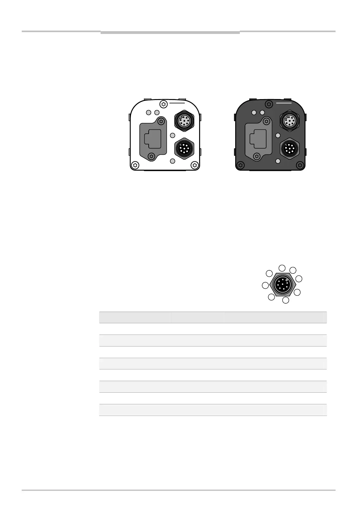
The electrical connections are done with M12 plug-connectors and an Ethernet RJ45
connector. There are three connectors on the back of the Ranger E and D.
encoder
Gigabit Ethernet
data
laser line
link
function on
power
encoder
Gigabit Ethernet
data
link
function on
power
laser line
Figure 9.5 – Back plate of the Ranger E and Ranger D respectively, with M12 connectors,
Ethernet connector, and LEDs
The LEDs on the back plate have the following functions:
LED When lit
On The Ranger is powered.
Link The Ranger is connected to an Ethernet network.
Data The Ranger is sending data over the Ethernet connection.
Function Reserved
Power I/O connector (male)
Pin Color* Signal Description
1 White In1 Enable (24 V)
2 Brown Power Power supply (24 V)
3 Green Out1 Reserved (B-type)
4 Yellow In2 Reset (24 V)
5 Gray TRA TRA, RS-485
6 Pink TRB TRB, RS-485
7 Blue GND Ground
8 Red Out2 Laser trigger (TTL)
*Color is valid for cable type DOL-1208-
1
2
3
4
5
6
7
8