Chapter 5 Reference Manual
Ranger E/D
58 ©SICK AG • Advanced Industrial Sensors • www.sick.com • All rights reserved
Configuring Ranger E and D
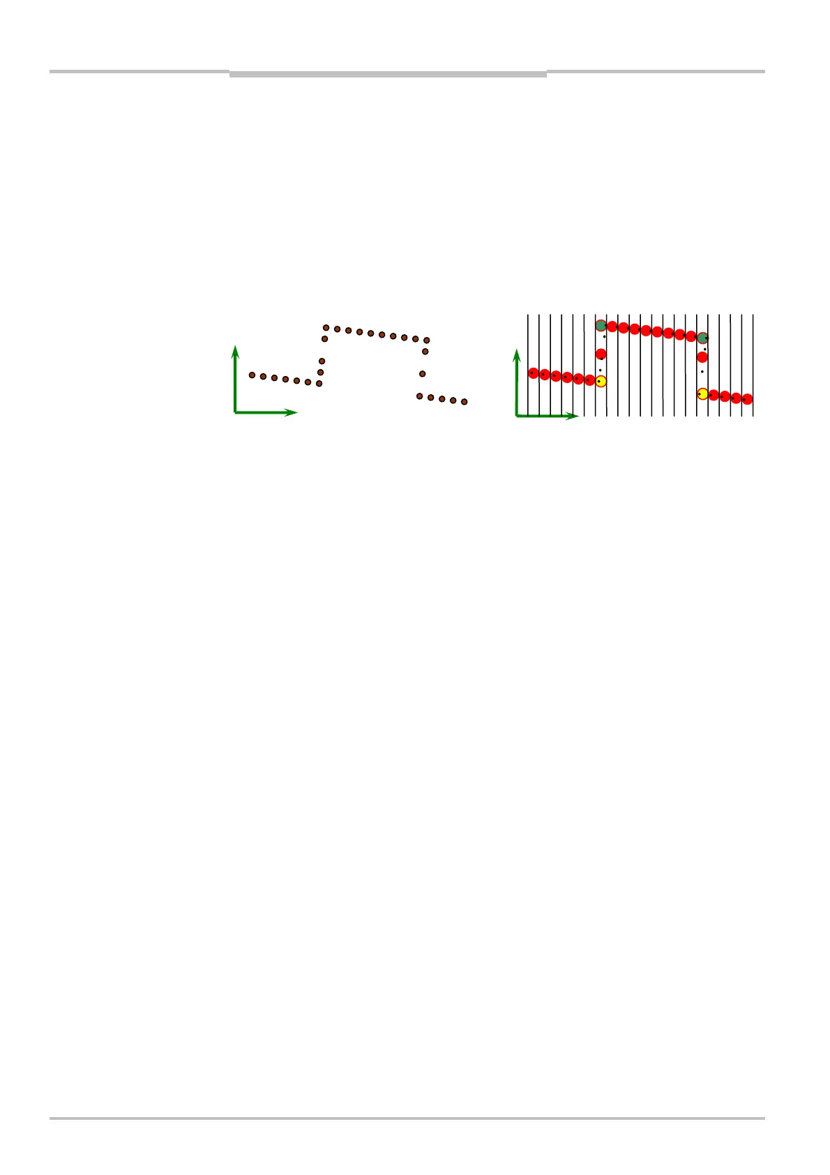
profile is represented in a discrete coordinate system, which is directly related to the real
world coordinate system. This means that the distance in X between two adjacent values
(pixels) in the profile is always the same regardless of where in the field of view they are
positioned. The image below shows how a set of calibrated data points translates into a
rectified profile. The final z value is represented as a floating point number to preserve the
full resolution. Notice the green and yellow resulting values at the edges in the profile. You
can select if you would like the rectification to return the maximum (green), minimum
(yellow) or average (red) pixel height within the discrete column. Selecting the average will
be better from a SNR (signal-to-noise) ratio since all the available data values are used. It
will however also result in false artifacts around sharp edges as in the image. In this case
it is usually a better choice to use the maximum or minimum value.
Figure 5.22 – Calibrated points and corresponding rectified profile
5.10.3 Physical Setup
Calibrated data can be obtained for an arbitrary physical setup. In the Ruler case, the
geometry of the system is given and can only be slightly modified by tilting the Ruler. In the
Ranger case, any setup can be calibrated. It is also possible to calibrate several range
components belonging to the same MultiScan setup.
It is important to remember that the calibration is always made in the laser plane. This
means that the obtained calibration LUT is always directly linked to the geometry of the
system. In the case of reverse ordinary geometry this means that a perpendicular coordi-
nate system is given whereas e.g. an ordinary geometry will have a skewed coordinate
system. The image below shows what this means in practice.
x
r
x
r
Calibrated (x, r) points Rectified profile