NOTICE
Risk of damage/malfunction due to incorrect PIN assignment
Incorrect wiring of the male connectors/female connectors can lead to damage to or
malfunctions in the system.
■
Observe data sheets provided by the cable manufacturer.
■
Observe the pin assignment.
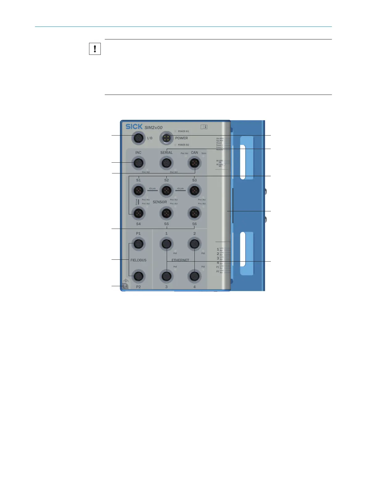
6.4 Overview of connections
1
I/O: Universal port with configurable inputs/outputs, opto-decoupled inputs as well as a
voltage supply for peripherals
2
POWER: Voltage supply input
3
INC: One incremental encoder In/Out or RS-422 as well as a voltage supply for peripher‐
als
4
SERIAL: One RS-232/RS-422/RS-485 or one INC In/Out as well as a voltage supply for
peripherals
5
CAN: Connection for the SICK CAN sensor network (receiver/transceiver) as well as a
voltage supply for peripherals
6
SENSOR 1-4: Four sensor connections with digital inputs/outputs and voltage supply. Can
be alternatively used as IO-Link master connections.
7
SENSOR 5-6: Two sensor connections with two configurable inputs/outputs, one dedi‐
cated input as well as a voltage supply. S6 is provided to supply and control the fan.
8
FIELDBUS: Two Ethernet-based fieldbus interfaces.
9
ETHERNET: Four Ethernet connections with PoE
ß
Functional ground connection: see "Important notes", page 19
à
Servicing panel
6 ELECTRICAL INSTALLATION
20
O P E R A T I N G I N S T R U C T I O N S | SIM2000 8023297//2021-06-22 | SICK
Subject to change without notice