Suitable cable lugs
•
Forked cable lug or ring cable lug
•
Width ≤ 10 mm
•
Hole diameter for screw: typically 4.1 mm
The functional earth must be connected in a low-inductance manner and with an
adequate cross-section while keeping the cable length as short as possible.
6.6 Pin allocation of the connections
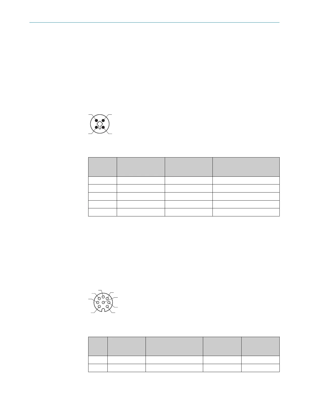
6.6.1 POWER IN
Figure 2: POWER IN pin assignment, M12 - 4-pin T-coded, male
Table 2: POWER IN
PIN Signal Color coding on the
SIM power cable e.g.,
6059939*
Function
1 + 24 V IN1 BN (brown) IN1 supply voltage
2 GND IN2 WH (white) Ground
3 GND IN1 BU (blue) Ground
4 + 24 V IN2 BK (black) IN2 supply voltage (redundant)
Housing - - Screen
*
SICK cables in the SIM accessories
Additional notes
•
Max. 7.5 A permanent load
•
Supply voltage “IN1” and “IN2” can be set up redundantly.
Observe the requirements for the design of overcurrent protective devices according to
EN 61010.
6.6.2 I/O
Figure 3: I/O pin assignment, M12 - 8-pin A-coded, female
Table 3: I/O connection
PIN Signal Function Factory settings Color coding of
open-ended SIM
I/O cables
1
1 Input 1 Isolated switching input – WH (white)
2 SensGND 1 Isolated GND input 3 – BN (brown)
6 ELECTRICAL INSTALLATION
22
O P E R A T I N G I N S T R U C T I O N S | SIM2000 8023297//2021-06-22 | SICK
Subject to change without notice