M
Michelle KennedyAug 7, 2025
How to fix contamination warning on SICK Accessories?
- JjwilsonAug 7, 2025
If you receive a contamination warning for your SICK Accessories, clean the front screens of the illumination unit and camera module.
How to fix contamination warning on SICK Accessories?
If you receive a contamination warning for your SICK Accessories, clean the front screens of the illumination unit and camera module.
What to do if SICK Accessories show contamination error?
If your SICK Accessories display a contamination error, you should clean the front screens of the illumination unit and camera module.
How to resolve an internal error on SICK Accessories?
To resolve an internal error with your SICK Accessories, try restarting the device via the Safety Designer or interrupt the voltage supply for at least 2 seconds. If the issue persists, replace the safety camera sensor and send it to the manufacturer for repair.
How to resolve temperature warning on SICK Accessories?
To resolve a temperature warning on your SICK Accessories, try mounting the heat sink.
Specifies the product covered by the document and its part number.
Identifies target audiences and lists relevant sections for each group.
Lists additional resources available online, such as data sheets and guides.
Provides essential general safety guidelines for product integration and use.
Defines the product's intended applications and suitable use cases.
Lists applications and conditions where the product is not suitable.
Specifies necessary qualifications for personnel involved in product setup and operation.
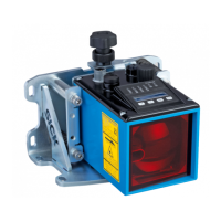
Provides a visual overview of the device and its main components.
Explains the device's operational principle and how it scans its surroundings.
Describes the meaning of the status LEDs on the device for diagnostics.
Details different types of detection fields and their applications.
Illustrates various practical applications such as hazardous area and access protection.
Covers prerequisites and general design considerations for implementation.
Specifies requirements for selecting an appropriate installation location.
Details measures to prevent device overheating and ensure availability.
Addresses potential sources of interference and mitigation strategies.
Explains how to prevent undetected areas and ensure full coverage.
Outlines how to calculate minimum distances for stationary setups.
Covers integrating the device into electrical control systems and safety functions.
Details how to integrate the device into a network and its topology.
Outlines the plan for performing thorough checks during commissioning and regular testing.
Provides instructions for attaching the heat sink to the device.
Explains how to mount the main device using available threaded holes.
Details how to connect the device via its M12 plug connector.
Explains the system connection using the 8-pin M12 connector.
Details the Ethernet connection configuration using the M12, 8-pin connector.
Describes the device's configuration state upon delivery.
Introduces the Safety Designer software for device configuration.
Provides step-by-step instructions for installing the configuration software.
Details how to configure devices directly connected to the network.
Explains how to configure devices using the device catalog without connection.
Explains how to open the device window for configuration and diagnostics.
Guides the configuration of general monitoring parameters and object resolution.
Introduces the 3D editor for detailed configuration of fields and ROIs.
Provides an overview of local input and output connections and signals.
Explains how to define and manage monitoring cases for different scenarios.
Details the process of saving and transferring configurations to the device.
Explains how to verify the configuration against safety requirements.
Outlines service functions for device management, including password handling.
Describes the procedure for switching on the device.
Covers necessary checks after commissioning or modifications for safety.
Explains the meaning of status LEDs for OSSDs and Ethernet connections.
Provides instructions for regular cleaning of the device's front screens.
Outlines procedures for regular thorough checks to ensure safety functions.
Lists fault indicators, their causes, and troubleshooting steps.
Explains how to use diagnostic tools like data recorder and message history.
Describes the data recorder tool for analyzing device signals.
Explains how to access and interpret the message history for events.
Details proper disposal procedures for the device according to regulations.
Presents detailed features, safety parameters, and interface specifications.
Details the device's response time based on multiple sampling settings.
Explains the OSSD testing procedure and timing.
Details scanning ranges for protective, contour detection, and ROI fields.
Provides dimensional drawings of the safety camera sensor and heat sink.
Lists the items included in the product's scope of delivery.
Specifies part codes and numbers for ordering the safety camera sensor.
Provides ordering information for mounting brackets.
Provides ordering information for the heat sink accessory.
Lists cleaning agents and related items for maintenance.
Details how to access conformity declarations and certificates.
Lists relevant standards and their regional equivalents.
Explains the usage of open source software and licensing terms.
Provides a checklist for initial commissioning and regular inspections.
| Brand | SICK |
|---|---|
| Model | safeVisionary2 |
| Category | Accessories |
| Language | English |