3 Product description
3.1 Device overview
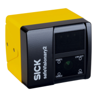
Device overview
Figure 2: Device overview
1
Illumination unit
2
Status indicators: Status LEDs
3
Camera module
4
System connection: Voltage supply, OSSDs and universal IO
5
Ethernet connection
Further topics
•
"E
lectrical installation", page 53
•
"Mounting", page 51
3.2 Structure and function
Structure and function
T
he safety camera sensor is an electro-sensitive protective device (ESPE) which scans
its surroundings three-dimensionally using infrared laser beams.
As soon as an object is situated in the protective field, the camera sensor signals
the detection by means of a signal change at the safety output. The machine or its
controller must safely analyze the signals (for example using a safety controller or a
safety relay) and stop the dangerous state.
The camera sensor operates according to the optical time-of-flight measurement princi‐
ple. It emits light pulses at regular, very short intervals. If the light strikes an object,
it is reflected. The camera sensor receives the reflected light. The camera sensor
calculates the distance to the object based on the time interval between the moment of
transmission and moment of receipt (∆t).
Field of view
T
he camera sensor has a field of view with an aperture angle of 68° × 58° (horizontal
× vertical).
For protective field evaluation, the field of view of the camera sensor is limited to 68°
× 42°. The full 68° × 58° field of view is available for all other safety functions, field
types, and for data output.
Detection zones of different sizes are created depending on distance z.
3 P
RODUCT DESCRIPTION
12
O P E R A T I N G I N S T R U C T I O N S | safeVisionary2 8025919/1I9E/2023-01-09 | SICK
Subject to change without notice

 Loading...


