Features Description
Multiple sampling At first, the object resolution and multiple sampling configured
f
or the monitoring plane apply for all fields. If necessary, you can
change these settings for each individual field.
For the contour detection field, sizes for openings in the floor are
also available when selecting the object resolution. The safety
camera sensor ignores gaps (openings) in the contour up to a cer‐
tain size. The cut-off path switches to the OFF state if the opening
exceeds the configured size. If you have activated the Reference
for increased scanning range setting, then only the 100x100 cm object
resolution for floor openings is available.
Object resolution
Contour detection field
R
eference contour
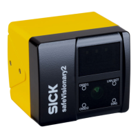
The safety camera sensor monitors a specific area in its surround‐
ings. This requires a reference image of the surroundings (refer‐
ence contour). The monitored area is the area of intersection
between the contour of the reference image and the projection of
the field geometry onto the reference contour.
You can assign a separate reference contour for each contour
detection field here. The Calibration data and Contours page can be
used to create the reference contours.
Contour detection field
T
olerance band
A contour has a positive and a negative tolerance band. The cut-
off path switches to the OFF state if the safety camera sensor
does not detect the contour within the tolerance band.
•
Positive tolerance (far): The tolerance away from the safety cam‐
era sensor
•
Negative tolerance (near): The tolerance toward the safety camera
sensor
Note "Properties of tolerance band for contour detection fields",
page 68
Partial checksum (field
g
eometry)
Shows the partial checksum for field geometries.
Properties of tolerance band for contour detection fields
•
T
o reliably detect an object, the distance values of the object must differ from the
reference contour by more than the configured tolerance band. With the default
setting, the tolerance band reliably detects the selected object resolution, even if
the object is in direct contact with the reference contour.
•
A smaller tolerance band can lead to unintended shutdowns of the machine due
to vibrations, measurement noise or thermal effects. Use a smaller tolerance band
only in exceptional cases, and in that case set a multiple sampling of 4x or higher.
•
A larger tolerance band may result in an object not being reliably detected if it is in
direct contact with the reference background. Check for consistent detection using
a dark test object of the same size. If the tolerance band is too large, either reduce
the value of the tolerance band or use other measures to prevent relevant objects
in direct contact with the reference contour from entering the hazardous area.
Minimum field geometry size
T
able 32: Minimum cuboid size
Object resolution Minimum cuboid size (W x D x H)
Hand
Arm
Leg
Body
300mm × 300mm × 300mm
40x40 cm (contour detection field) 400mm × 400mm × 400mm
100x100 cm (contour detection field) 1,000mm × 1,000mm × 1,000mm
7 CONFIGURATION
68
O P E R A T I N G I N S T R U C T I O N S | safeVisionary2 8025919/1I9E/2023-01-09 | SICK
Subject to change without notice

 Loading...


