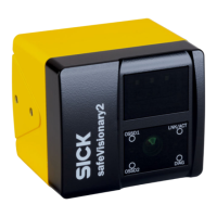
3.3 Status indicators
Status indicators
OSSD1
OSSD2
LNK/ACT
DIAG
OSSD1
O
SSD2
LNK/ACT
DIAG
Figure 4: Status indicators
T
able 3: Status indicators
LEDs Color Function
OSSD1 Green/yellow/red OSSD pair 1 status
OSSD2 Green/yellow/red OSSD pair 2 status
LNK/ACT Yellow/green Ethernet status
DIAG Green/yellow/red Diagnostics status
W
arning field status
Further topics
•
"St
atus indicators", page 81
•
"Fault indicators", page 84
3.4 Product characteristics
3.4.1 Coordinate system
Origin of the device coordinate system
T
he coordinate origin of the device coordinate system is at the point where the optical
axis and the camera front screen (outer surface) intersect.
The Z axis runs along the optical axis. Looking in the direction of the optical axis, the
X-axis points to the left and the Y-axis points upwards.
3 P
RODUCT DESCRIPTION
14
O P E R A T I N G I N S T R U C T I O N S | safeVisionary2 8025919/1I9E/2023-01-09 | SICK
Subject to change without notice

 Loading...


