PIN Signal Function Factory settings Color coding of
open-ended SIM
I/O cables
1
3 Input 2 Isolated switching input
–
GN (green)
4 SensGND2 Isolated GND input 4 YE (yellow)
5 Input 3/Output 3 Configurable switching
input/output
GY (gray)
6 Input 4/Output 4 Configurable switching
input/output
PK (pink)
7 24 V OUT Supply voltage, peripherals BU (blue)
8 GND - RD (red)
Housing – Screen
1
SICK cables in the SIM accessories
Additional notes:
•
Connection to control cabinet to connect devices directly
•
2 GPIOs and 2 isolated inputs
•
Max. 0.5 A output for supply voltage connection (compliant with LPS)
•
Digital outputs can be configured as inputs
•
Outputs:
°
Max. current output: 100 mA
°
Min. high output logic level: VCC - 3 V
°
Max. low output logic level: 3 V
°
Push-pull
°
Max. output frequency: 10 kHz
•
Inputs:
°
Min. high input logic level: 12 V
°
Max. low input logic level: 4 V
°
Input 1 - 2 (isolated): maximum 30 kHz
°
Input 3 - 4: Max. input frequency: 30 kHz
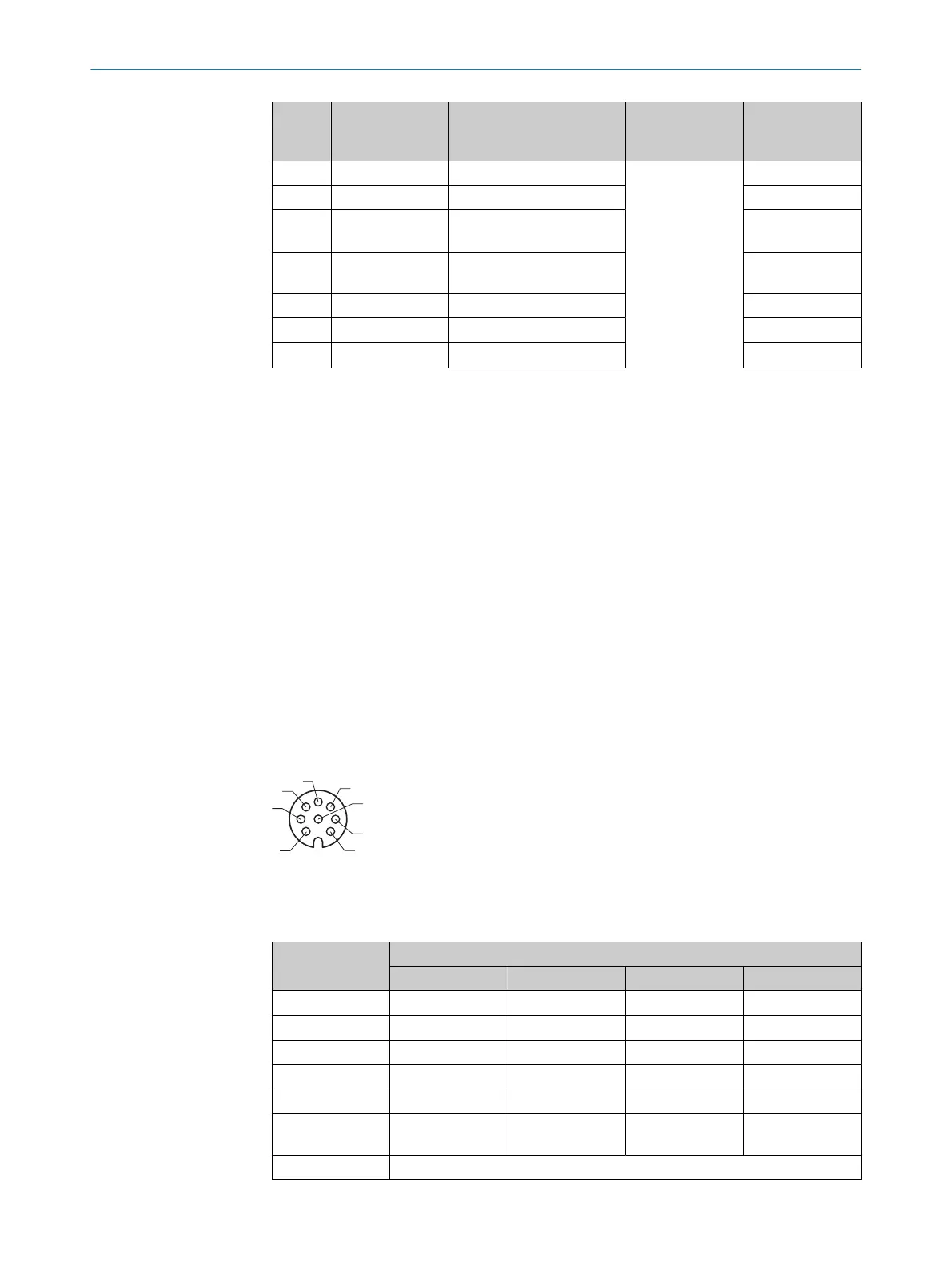
6.6.3 INC
Figure 4: Incremental pin assignment, M12 - 8-pin A-coded, female
Table 4: Incremental connections for encoders, can also be used as serial connections for
RS-422
PIN Mode
RS-422
*
RS-232 RS-485 INC
1 T- - - A- (in/out)
2 T+ - - A+ (in/out)
3 R- - - B- (in/out)
4 R+ - - B+ (in/out)
5 - - - Z- (not supported)
6 - - - Z+ (not sup‐
ported)
7 GND (ground)
ELECTRICAL INSTALLATION 6
8023297//2021-06-22 | SICK O P E R A T I N G I N S T R U C T I O N S | SIM2000
23
Subject to change without notice