PIN Mode
RS-422
*
RS-232 RS-485 INC
8 24 V (supply voltage for peripherals, configurable, deactivated in factory
condition)
Housing Screen
*
Standard configuration
Additional notes
•
Max. 0.5 A output for supply voltage connections (compliant with LPS)
•
Frequency: max. 2 MHz
•
TTL encoders use RS422 and can be connected via the INC interface.
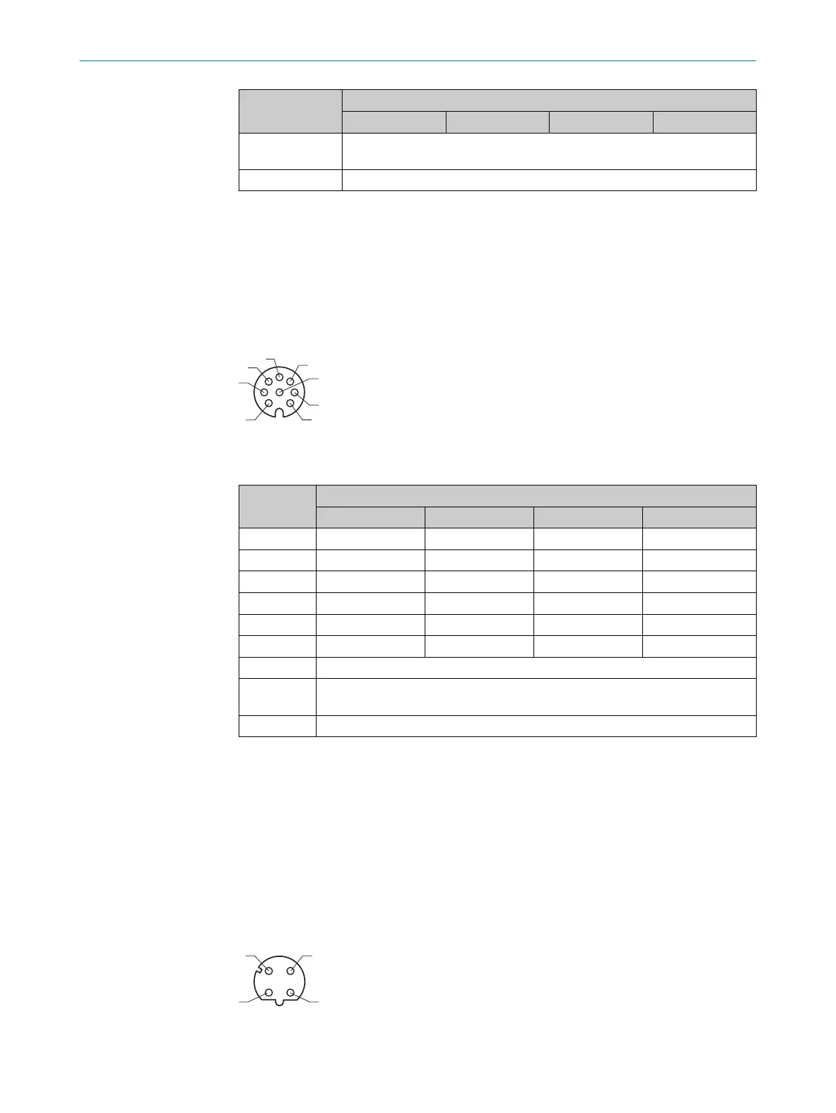
6.6.4 SERIAL
Figure 5: Serial pin assignment, M12 – 8-pin A-coded, female
Table 5: Serial connections, can also be used as an incremental connection
PIN Mode
RS-422 RS232
*
RS-485 INC
1 - - - A- (in/out)
2 - - - A+ (in/out)
3 T- - Rx/Tx- (B) B- (in/out)
4 T+ TxD Rx/Tx+ (A) B+ (in/out)
5 R- - - Z- (not supported)
6 R+ RxD - Z+ (not supported)
7 GND (ground)
8 24 V (supply voltage for peripherals, configurable, deactivated in factory condi‐
tion)
Housing Screen
*
Standard configuration
Additional notes
•
Max. 1 A output for supply voltage connections (compliant with LPS)
•
Data transmission rates:
°
RS-232: 115.2 kBaud
°
RS-422: 2 MBaud
°
RS-485: 2 MBaud
•
TTL encoders use RS422 and can be connected via the SERIAL interface.
6.6.5 FBUS
Figure 6: Fieldbus pin assignment, M12 – 4-pin D-coded, female
6 ELECTRICAL INSTALLATION
24
O P E R A T I N G I N S T R U C T I O N S | SIM2000 8023297//2021-06-22 | SICK
Subject to change without notice