6.4.1 TiMxxx-20xxxxx
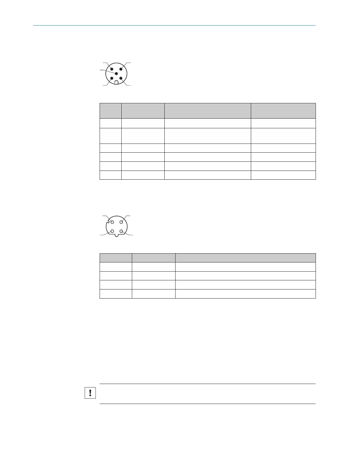
Power connection
Table 7: Male connector, M12, 5-pin, A-coded
Pin Signal Function Wire colors of connecting
cable with flying leads
1
1 V
S
Supply voltage Brown
2 SYNC/ Device
Ready
Synchronization digital output White
3 GND Ground Blue or Yellow
4 – Reserved, do not wire this PIN! –
5 – Reserved, do not wire this PIN! –
– – Screen –
1
Example values when using the connecting cable part number 6036159 (5 m). Signal assignment and
wire colors can vary when using other connecting cables.
"Ethernet" connection
Table 8: Female connector, 4-pin, D-coded
Contact Labeling Description
1 TX+ Sender+
2 RX+ Receiver+
3 TX- Sender-
4 RX- Receiver-
6.4.2 USB interface
The Ethernet interface is recommended as a communication interface.
If using the USB interface, please note:
•
Use a high-speed UBS cable, maximum length of cable 3 m.
•
The connection may be interrupted due to ESD/EMC influences. If necessary:
Disconnect USB cable from the device, then reconnect it. Restart communication
via SOPAS ET software (“Online” button).
6.5 Connecting the device electrically
NOTICE
Observe the wiring instructions, see "Wiring instructions", page 28.
1. Ensure the voltage supply is not connected.
2. Connect the device according to the connection diagram, see "Connection dia‐
gram", page 28.
ELECTRICAL INSTALLATION 6
8025144//2021-07-21 | SICK O P E R A T I N G I N S T R U C T I O N S | TiM55x/56x/57x/58x
29
Subject to change without notice