6.6 Wiring the SYNC/Device Ready digital output
The SYNC/Device Ready digital output is used to issue an error and a regular index
pulse.
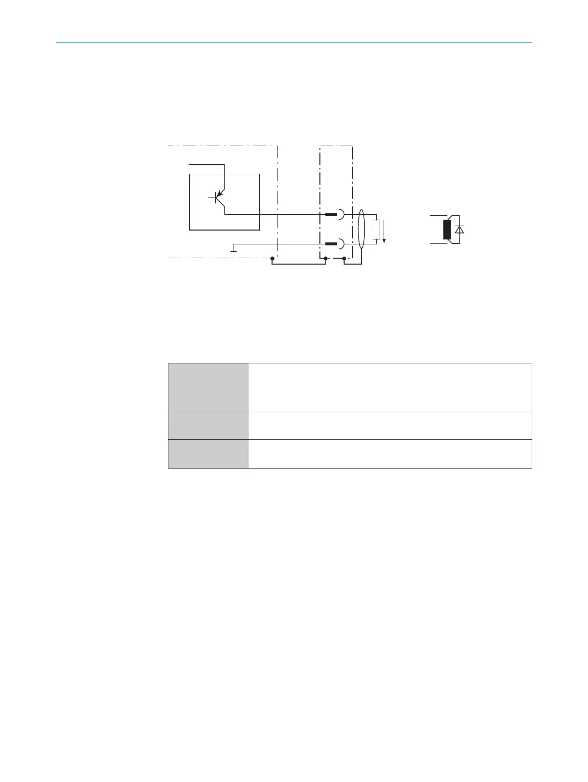
The structure and wiring principle of the digital output are shown below.
Device 1
OUT X 2
X
Y
GND
V
out
3
4
Figure 23: Wiring of the SYNC/Device Ready digital output
1
Device
2
SYNC/Device Ready output signal
3
Output voltage V
out
4
If an inductive load is present: Provide an arc-suppression circuit at the digital switching
output. Attach a freewheeling diode directly to the load for this purpose.
Switching behavior PNP switching against supply voltage UV
Resting level: High (device ready)
working level: Low (error), low pulse (15 Hz, index, corresponds to meas‐
urement at 90°)
Features Short-circuit protected and temperature protected
Not electrically isolated from supply voltage U
v
Electrical values 0 V ≤ V
out
≤ V
S
(V
S
– 1.5 V) ≤ V
out
≤ V
S
at I
out
≤ 100 mA
Longer connecting cables at the digital output of the device should be avoided due to
the resulting fall in voltage. This is calculated as follows:
Δ U = (2 x length x current) : (conductance value x cross-section)
Conductance value for copper: 56 m/Ω mm
2
.
6
ELECTRICAL INSTALLATION
30
O P E R A T I N G I N S T R U C T I O N S | TiM55x/56x/57x/58x 8025144//2021-07-21 | SICK
Subject to change without notice