°
the chosen physical version of the host interface
°
the data transmission rate set in the device
For further information, see "Wiring data interfaces", page 36.
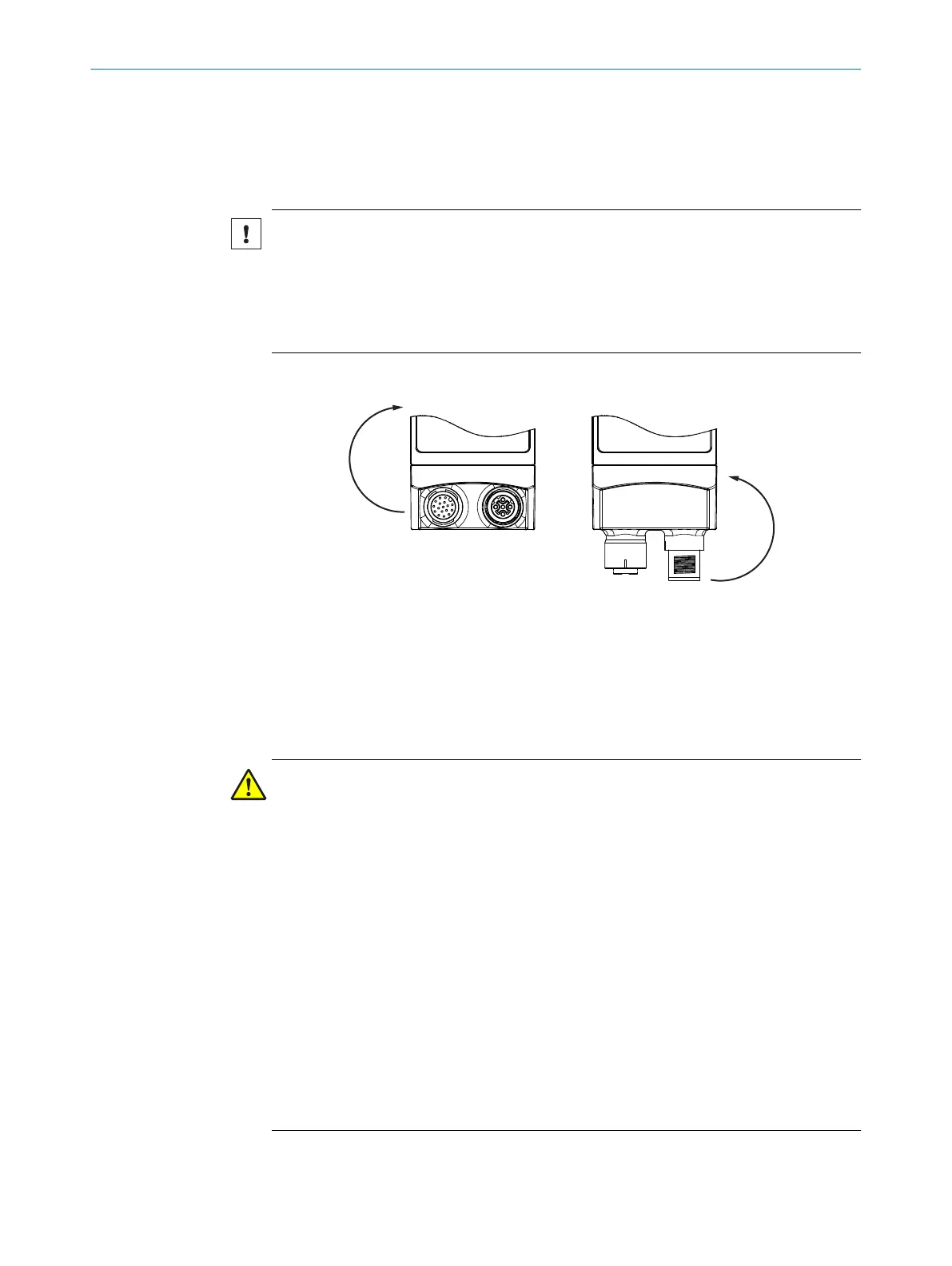
6.1.2 Note on the swivel connector
NOTICE
Damage to the connector from over-rotation!
The swivel connector has two opposite end positions.
■
Do not rotate the connector from either of the two end positions by more than
180° in the opposite direction. Do not exceed the respective limit position.
■
Carry out the rotational movement slowly.
A B
B A
Maximum
180°!
3
Maximum
180°!
3
End position 1 1 End position 2 2
Figure 12: End positions of the swivel connector
1
End position 1
2
End position 2
3
Maximum 180°
6.1.3 Prerequisites for safe operation of the device
WARNING
Risk of injury and damage caused by electrical current!
As a result of equipotential bonding currents between the device and other grounded
devices in the system, faulty grounding of the device can give rise to the following dan‐
gers and faults:
■
Dangerous voltages are applied to the metal housings.
■
Devices will behave incorrectly or be destroyed.
■
Cable shielding will be damaged by overheating and cause cable fires.
Remedial measures
■
Only skilled electricians should be permitted to carry out work on the electrical sys‐
tem.
■
If the cable insulation is damaged, disconnect the voltage supply immediately and
have the damage repaired.
■
Ensure that the ground potential is the same at all grounding points.
■
Where local conditions do not meet the requirements for a safe earthing method,
take appropriate measures (e.g., ensuring low-impedance and current-carrying
equipotential bonding).
6 ELECTRICAL INSTALLATION
28
O P E R A T I N G I N S T R U C T I O N S | InspectorP621 8024439//2019-06 | SICK
Subject to change without notice
 Loading...

