á
Optional CMC600 parameter cloning module to use the external digital inputs and outputs of the device (not sup‐
ported).
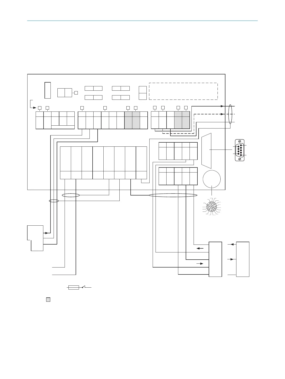
13.3.2 Wiring overview of the CDB650-204
CMC600 parameter cloning module
(optional) 2
Term CAN
Term 485RS
SGND - GND
422 485
ONOFF
NO
YES
ONOFF
ONOFF
S2 S3
S7S6
S4
CMC
ONOFF
POWER
S1
30 31 32 33 34
CAN_H
CAN_L
T+
R+
GND
40 41 42 43 44
CAN_H
CAN_L
T‒/TxD
R‒/RxD
GND
AUX interface 5
U
IN
U
IN
GND
GND
Shield
Shield
Shield
Shield
1 2 3 4 5 6 7 8
LEDs
= ß
V
S
V
S
Out
GND
Result 1 4
- e.g. PLC 3
GND
Result 2 4
- Device 9
Pin
2: RxD
3: TxD
5: GND
Host
TD‒
TD+
RD+
RD‒
TxD
Host
RxD
GND
GND
RS-232
2 A T
F
SENSOR
50 51 52 53 54
RES/
OUT 3
RES/
OUT 4
Ext. Illum.
TR
L+
GND
20 21 22 23 24
GND
RES/
OUT 1
RES/
OUT 2
EXT.
OUT 1
EXT.
OUT 2
10 11 12 13 14 15 16 17 18
U
IN
*
U
IN
*
SGND
SGND
SGND
EXT.
IN 1
SENS/
IN 1
SENS/
IN 2
EXT.
IN 2
RS-232
3
1
7
2
6
5
4
8
13
14
17
15
9
10
12
16
11
8
1
CDB650-204
V
S
- U
IN
-
F
S 1
- U
IN
*
- PC
6
7
à
5
1
9
6
RS-422
Figure 26: Connection of device and peripherals to the CDB650-204 connection module (overview)
1
External trigger sensor
2
CMC600 parameter cloning module (not supported)
3
e.g. PLC (programmable logic controller)
4
Name of the digital output
5
Auxiliary interface “Aux”
6
Male connector, D-Sub, 9-pin
13 ANNEX
56
O P E R A T I N G I N S T R U C T I O N S | InspectorP621 8024439//2019-06 | SICK
Subject to change without notice
 Loading...

