Device 1 CDB650-204 Host
1
.
.
.
TxD
RxD
RxD
TxD
GND
GND
GND
12
1
6
12
6
43
T‒/TxD
44
R‒/RxD
42
GND
6
Shield
RS-232 RS-232
422
485
S6 : RS
ON
OFF
S7: Term 485
S6
422485
3
1
7
2
6
5
4
8
13
14
17
15
9
10
12
16
11
3
1
7
2
6
5
4
8
13
14
17
15
9
10
12
16
11
Cable 2
4 3
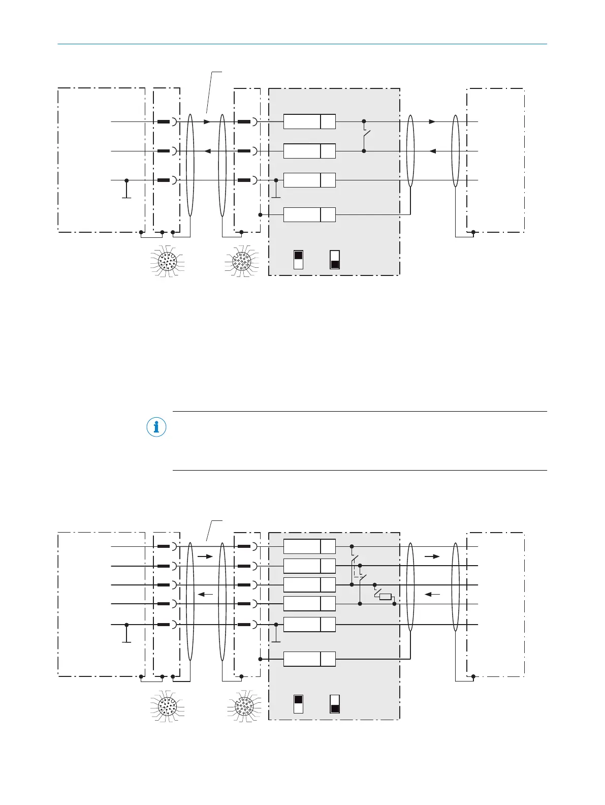
Figure 28: Wiring data interface RS-232 of the device in the connection module CDB650-204
1
Device
2
Connection cable 1:1 (female connector, M12, 17-pin, A-coded/male connector, M12, 17-pin, A-coded)
3
Connection module: female connector, M12, 17-pin, A-coded
4
Device: male connector, M12, 17-pin, A-coded
NOTE
Control the RS-232 data interface in the device with the API functions. In order to acti‐
vate the RS-232 data interface, use an installed SensorApp which contains this func‐
tion.
13.3.5 Wiring serial host interface RS-422 of the device in CDB650-204
CDB650-204 Host
1
.
.
.
TD+
TD‒
RD+
RD‒
RD+
RD‒
TD+
TD‒
GND
GND
GND
11
12
1
5
5
6
11
12
6
33
T+
43
T‒/TxD
34
R+
44
R‒/RxD
42
GND
6
Shield
RS-422 RS-422
422
485
S6 : RS
ON
OFF
S7: Term 485
S6
422
S7
OFF
120 Ω
485
3
1
7
2
6
5
4
8
13
14
17
15
9
10
12
16
11
3
1
7
2
6
5
4
8
13
14
17
15
9
10
12
16
11
Device 1
Cable 2
4 3
Figure 29: Wiring data interface RS-422 of the device in the connection module CDB650-204
13 ANNEX
58
O P E R A T I N G I N S T R U C T I O N S | InspectorP621 8024439//2019-06 | SICK
Subject to change without notice
 Loading...

