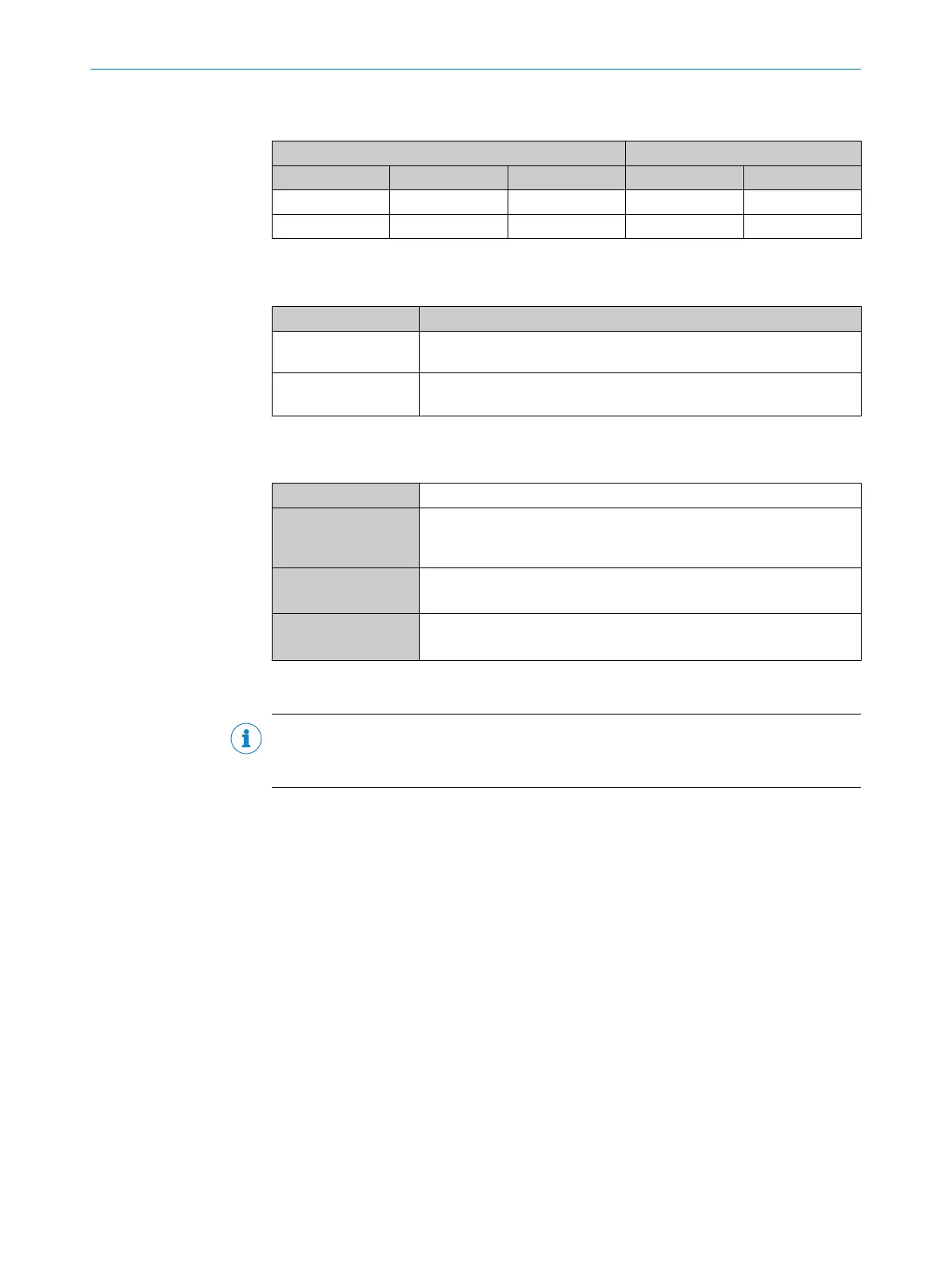
Table 19: Assignment of placeholders to the digital inputs
CDM420-0006 Device
Terminal A Signal B Pin C Pin D Sensor E
38 Sensor 1 14 10 1
28 Sensor 2 4 15 2
Function of switch S6
Table 20: Switch S6: SGND - GND
Switch setting Function
ON GND of the trigger sensor connected with GND of CDM420-0006 and
GND of the device
OFF Trigger sensor connected potential-free at CDM420-0006 and device.
Common, isolated reference potential of all digital inputs is SGND.
Characteristic data of the digital inputs
Table 21: Characteristic data of the digital inputs “Sensor 1” and “Sensor 2”
Type Switching
Switching behavior Power to the input starts the assigned function, e.g. start analysis.
Default setting in the device: logic not inverted (active high), debounce
time 10 ms
Properties
•
Opto-decoupled, reverse polarity protected
•
Can be wired with PNP output of a trigger sensor
Electrical values Low: V
in
1)
≤ 2 V; I
in
2)
≤ 0.3 mA
High: 6 V ≤ V
in
≤ 30 V; 0.7 mA ≤ I
in
≤ 5 mA
1)
Input Voltage
2)
Input current
NOTE
Control the digital inputs in the device with the API functions. In order to assign the digi‐
tal inputs functions, use an installed SensorApp which contains this function.
13.4.8 Wiring digital outputs of the device in the CDM420-0006
13 ANNEX
70
O P E R A T I N G I N S T R U C T I O N S | InspectorP621 8024439//2019-06 | SICK
Subject to change without notice
 Loading...

