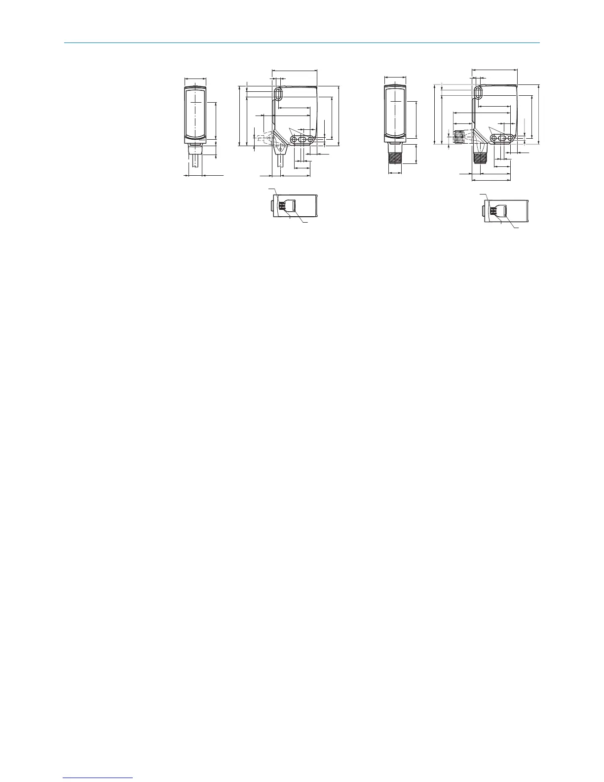
Figure 1: Dimensional drawing 1, cable
1
Center of optical axis
2
Fixing hole, Ø 4.1 mm
3
Connection
4
LED indicator green: Supply voltage
active
5
LED indicator yellow: Status of
received light beam
6
BluePilot blue: Alignment aid
Figure 2: Dimensional drawing 2, male con‐
nector
4 Mounting
Mount the sensor and the reflector using suitable mounting brackets (see the SICK
range of accessories). Align the sensor and reflector with each other.
Note the sensor's maximum permissible tightening torque of < 1,3 Nm.
5 Electrical installation
The sensors must be connected in a voltage-free state (U
V
= 0 V). The following informa‐
tion must be observed, depending on the connection type:
– Male connector connection: Note pin assignment
– Cable: wire color
Only apply voltage/switch on the voltage supply (U
V
> 0 V) once all electrical connec‐
tions have been established.
Explanations of the connection diagram (Tables 1 and 2):
Alarm = alarm output (see Table 4)
Health = alarm output (see Table 4)
MF (pin 2 configuration) = external input, teach-in, switching signal
Q
L1
/ C = switching output, IO-Link communication
OPERATING AND STATUS INDICATORS 3
8022197 | SICK
Subject to change without notice
5