Modes / func‐
tions
Mode Description
Teach-in
Single value
teach-in (BGS &
FGS)
The sensing range is defined by teaching in at one
single set point.
Two value teach-
in (BGS)
The sensing range is defined by teaching in at
two set points (object leading edge/rear edge). The
sensing range is placed in the center of the two set
points.
Manual With “Manual” teach-in the switching distance can
be set at a fix value.
Output - Configu‐
ration of Q1 and
Q2
PNP PNP output
NPN NPN output
Push-pull Push-pull output
LO Light operate (Q)
DO Dark operate (Q/)
3.5 IO-Link communication interface
The product comes with the IO-Link communication interface.
IO-Link communication is a master-device communication system.
The product can be operated in standard I/O mode (SIO) or IO-Link mode (IOL). All
automation functions and other parameter settings are effective in IO-Link mode and in
standard I/O mode.
The following functions are supported via the standard IO-Link communication inter‐
face:
•
Flexible sensor settings
•
Digital transmission of sensor signals to the IO-Link Master
•
Visualization and configuration of the sensor
•
Diagnostics /condition monitoring
•
Device identification
•
Easy device replacement
•
Events
A detailed description of the configurable functions and associated indices can be
found in the “IO-Link description” technical Information: Technical Information: Photo‐
electric sensors, SICK Smart Sensors / IO-Link.
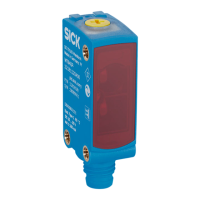
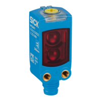
4 Mounting
Mounting with the background suppression principle of operation
Mount the sensor using a suitable mounting bracket (see the SICK range of accesso‐
ries).
OPERATING INSTRUCTIONS
9382969/2024-02-23 | SICK O P E R A T I N G I N S T R U C T I O N S | WTM10L
45
Subject to change without notice
en