5.4 Integration of the sensor in IO-Link mode
To operate the product in IO-Link mode, it must be connected to a suitable IO-Link
Master. This is used for further integration into the control system.
NOTE
The cable length between the IO-Link Master and IO-Link device: maximum 20m.
Details on integration can be found in the detailed IO-Link description: Technical Infor‐
mation: Photoelectric sensors, SICK Smart Sensors / IO-Link.
NOTE
After successful connection of the product to the IO-Link Master, the green (Power) LED
flashes to indicate a functioning IO-Link communication between the master and device.
6 Commissioning
6.1 Videos
The following video show individual steps for commissioning:
Table 6: Videoübersicht
Commissioning of the WTM10L senosr
https://video.sick.com/media/t/0_538a7d0l?
st=70
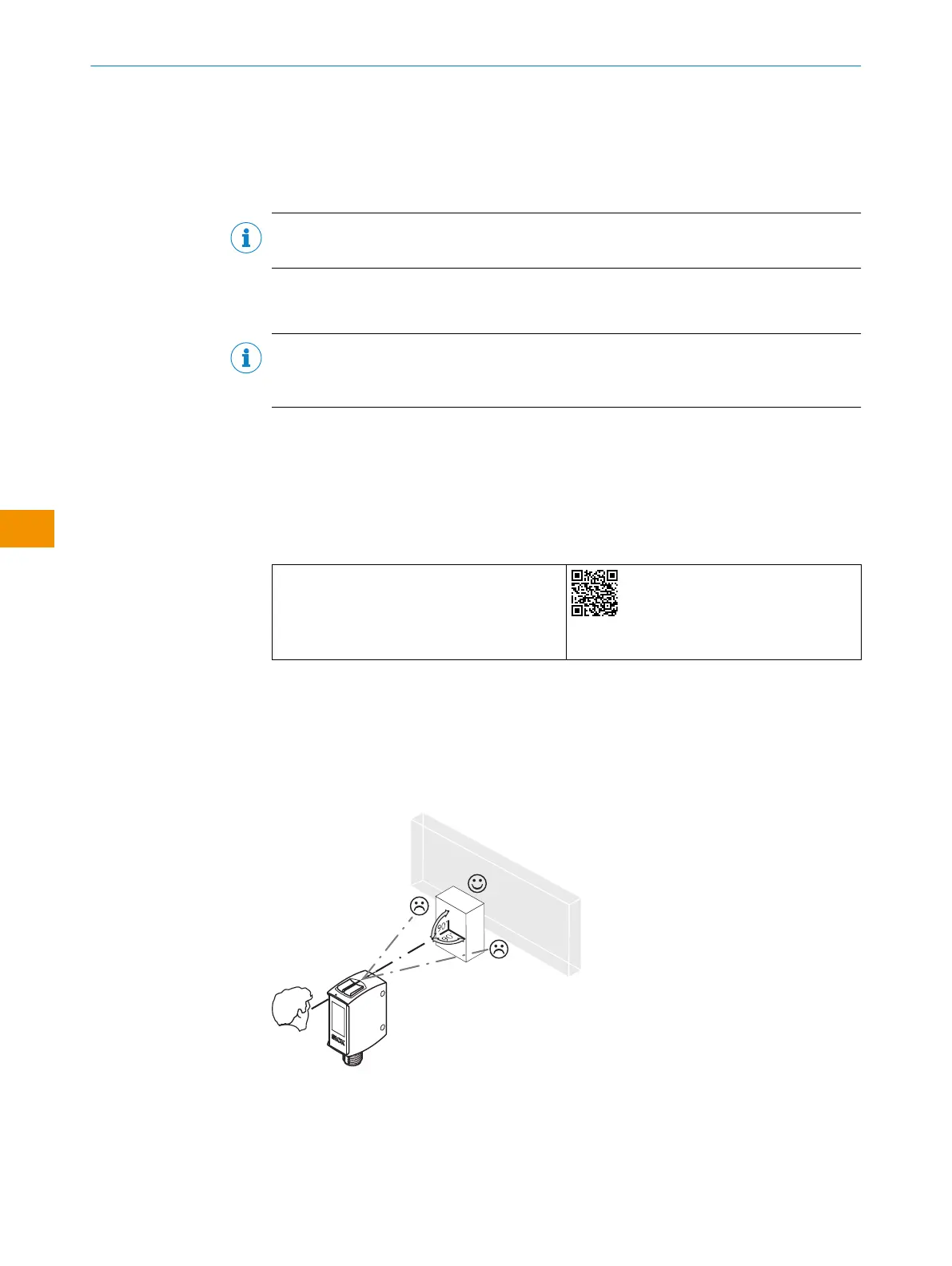
6.2 Alignment
Alignment with background suppression:
Align the sensor with the object. Select the position so that the red emitted light beam
hits the center of the object. You must ensure that the optical opening (front screen) of
the sensor is completely clear [see figure 8].
Figure 8: Alignment
Alignment with foreground suppression:
Align the sensor with the background. You must ensure that the optical opening
(front screen) of the sensor is completely clear figure 9].
OPERATING INSTRUCTIONS
50
O P E R A T I N G I N S T R U C T I O N S | WTM10L 9382969/2024-02-23 | SICK
Subject to change without notice
en