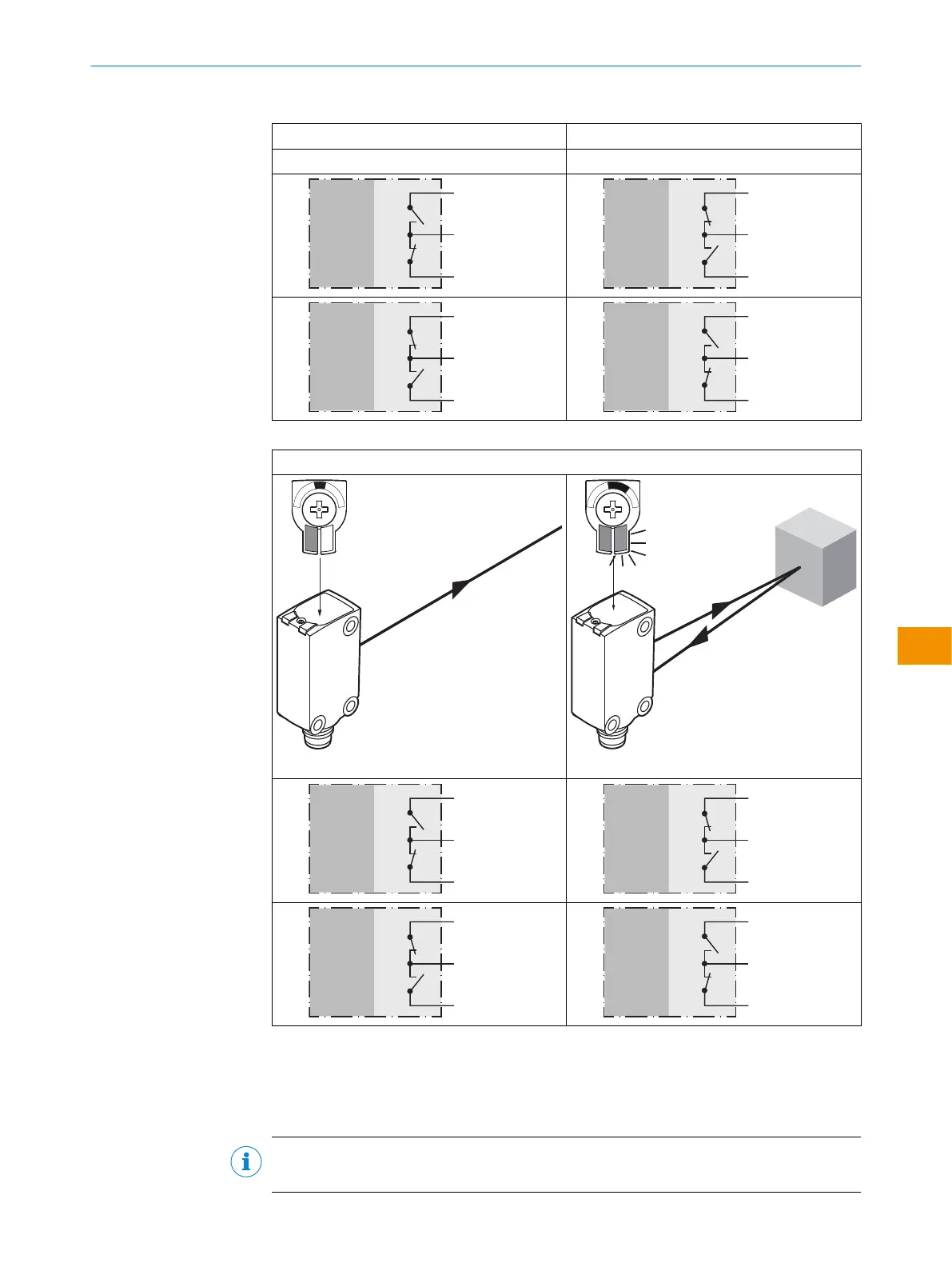
Tabella 5: Push-pull, PNP, NPN
MultiMode 1/3/5/6: MultiMode 1/3/5/6:
MultiMode 2: MultiMode 2:
Push-pull
PNP
NPN
+ (L+)
Q ≤ 100 mA
‒ (M)
Push-pull
PNP
NPN
+ (L+)
Q ≤ 100 mA
‒ (M)
Push-pull
PNP
NPN
+ (L+)
Q ≤ 100 mA
‒ (M)
Push-pull
PNP
NPN
+ (L+)
Q ≤ 100 mA
‒ (M)
Tabella 6: Push-pull, PNP, NPN
MultiMode 4:
Q
L1
/Q
L2
Push-pull
PNP
NPN
+ (L+)
Q ≤ 100 mA
‒ (M)
Push-pull
PNP
NPN
+ (L+)
Q ≤ 100 mA
‒ (M)
Push-pull
PNP
NPN
+ (L+)
Q ≤ 100 mA
‒ (M)
Push-pull
PNP
NPN
+ (L+)
Q ≤ 100 mA
‒ (M)
5.4 Integrazione del sensore in modalità IO-Link
Per utilizzare il prodotto in modalità IO-Link, è necessario collegarlo a un IO-Link Master
adeguato. Questo viene utilizzato per un'ulteriore integrazione nel sistema di controllo.
INDICAZIONE
Lunghezza del cavo tra l’IO-Link Master e l’IO-Link Device: massimo 20m.
ISTRUZIONI PER L’USO
8028212/2023/10/20 | SICK I S T R U Z I O N I P E R L ’ U S O | WTM4S
143
Contenuti soggetti a modifiche senza preavviso
it