Push-pull
PNP
NPN
+ (L+)
Q ≤ 100 mA
‒ (M)
Push-pull
PNP
NPN
+ (L+)
Q ≤ 100 mA
‒ (M)
Push-pull
PNP
NPN
+ (L+)
Q ≤ 100 mA
‒ (M)
Push-pull
PNP
NPN
+ (L+)
Q ≤ 100 mA
‒ (M)
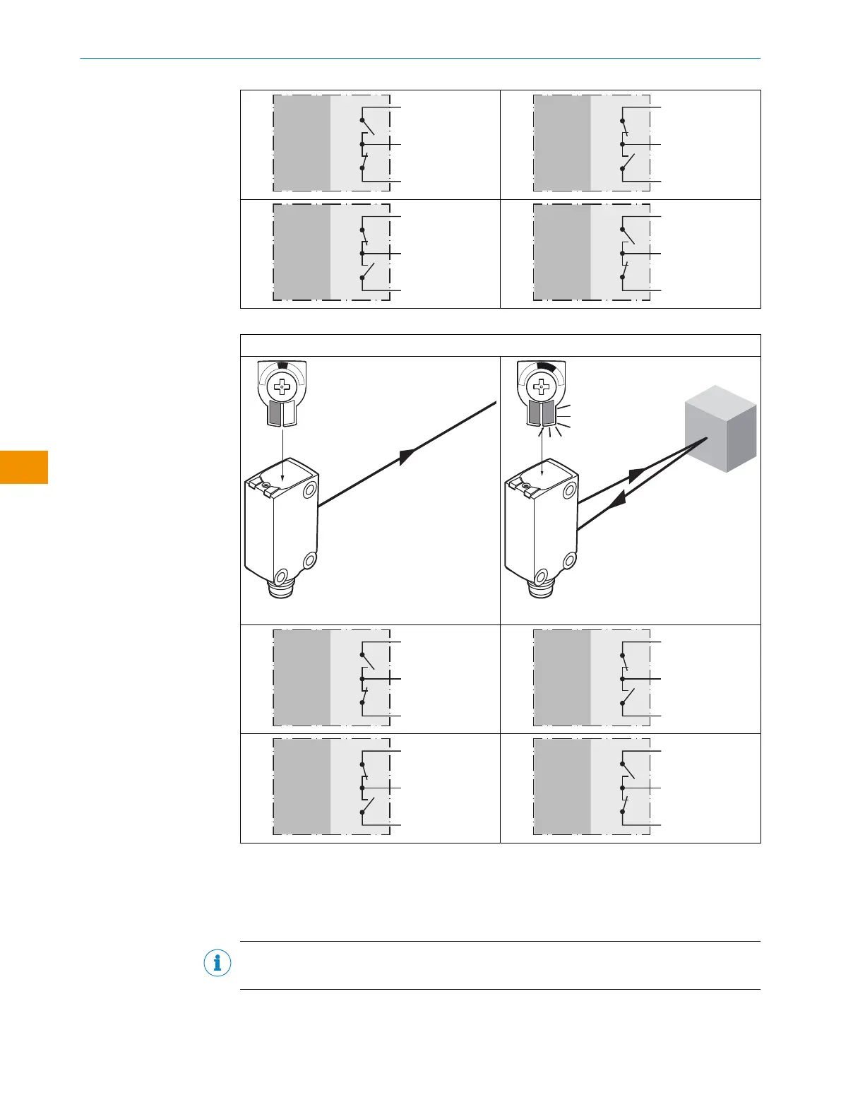
Table 6: Push-pull, PNP, NPN
MultiMode 4:
Q
L1
/Q
L2
Push-pull
PNP
NPN
+ (L+)
Q ≤ 100 mA
‒ (M)
Push-pull
PNP
NPN
+ (L+)
Q ≤ 100 mA
‒ (M)
Push-pull
PNP
NPN
+ (L+)
Q ≤ 100 mA
‒ (M)
Push-pull
PNP
NPN
+ (L+)
Q ≤ 100 mA
‒ (M)
5.4 Integration of the sensor in IO-Link mode
To operate the product in IO-Link mode, it must be connected to a suitable IO-Link
Master. This is used for further integration into the control system.
NOTE
The cable length between the IO-Link Master and IO-Link device: maximum 20m.
Details on integration can be found in the detailed IO-Link description: Technical Infor‐
mation: Photoelectric sensors, SICK Smart Sensors / IO-Link.
OPERATING INSTRUCTIONS
46
O P E R A T I N G I N S T R U C T I O N S | WTM4S 8028212/2023/10/20 | SICK
Subject to change without notice
en