6
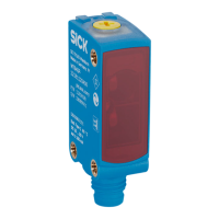
Elementos de control y de ajuste
12.1 (0.48)
M8x1
7.6 (0.3)
8.9 (0.35)
18.6 (0.73)
11.3 (0.44)
3.7
(0.15)
18.6 (0.73)
25.4 (1)
12 (0.47)
30.5 (1.2)
6
5
4
3
1
2
5 5
Figura 16: WTx4ST, conector macho M8
1
Orientación preferente del objeto
2
Centro del eje óptico del receptor
3
Centro del eje óptico del emisor
4
Conexión
5
Rosca de fijación M3
6
Elementos de control y de ajuste
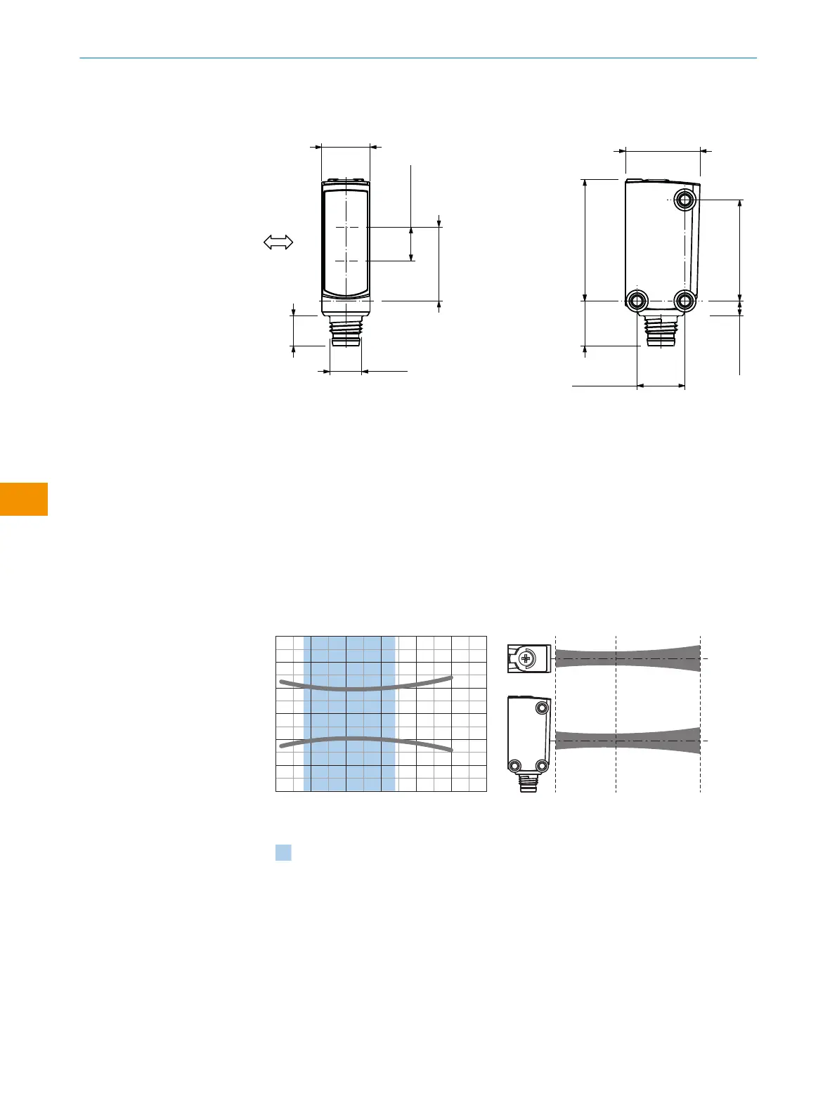
11.3 Diagramas del spot
MultiMode 1, 2, 3, 4, 5, M
0
Distance in mm (inch)
Dimensions in mm (inch)
4
(0.16)
6
(0.24)
–6
(–0.24)
–4
(–0.16)
0
2
(0.08)
–2
(–0.08)
Recommended sensing range for
the best performance
150
(5.91)
100
(3.94)
50
(1.97)
200
(7.87)
250
(9.84)
300
(11.81)
10
(0.39)
250
(9.84)
110
(4.33)
Figura 17: WTB4SP-xxxxx1xx
INSTRUCCIONES DE USO
96
I N S T R U C C I O N E S D E U S O | WTM4S 8028212/2023/10/20 | SICK
Sujeto a cambio sin previo aviso
es