12.1 PREREGOLAZIONE
DEL FRENO
Valori da impostare prima di instal-
lare le funi di sospensione dell’ar-
gano:
-controllare che il freno non abbia
subito danni durante il trasporto,
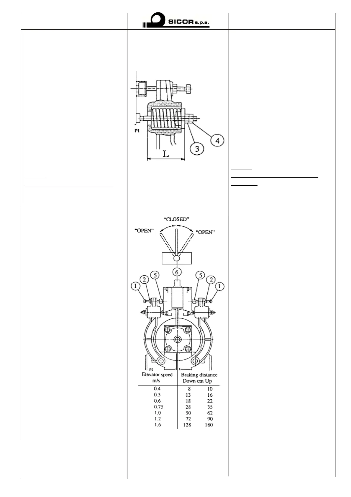
-allentare e togliere i dadi (4) e (3),
quindi rimuovere la carta di prote-
zione sia dal tamburo freno che dai
ferodi,
-regolare la molla (vedi tabella)
mediante il relativo dado (3),
-fissare la regolazione mediante il
controdado (4),
-per la regolazione della corsa vedi
il rispettivo paragrafo.
OTA:
Ruotare il volano manualmente.
12.2 REGOLAZIONE DEL
FRENO
Il freno è provvisto di due magneti
separati che rendono i ceppi indi-
endenti l’uno dall’altro.
12.2.1 REGOLAZIONE DELLA
CORSA MR17
-Allentare i controdadi (2) di en-
trambi i ceppi freno e svitare la vite
di regolazione (1) lasciando un gio-
co di 4-5 mm fra la vite ed il cap-
ello perno elettromagnete (5),
-girare la leva aprifreno (6) nella
osizione “aperto”,
-avvitare le viti di regolazione (1)
manualmente fino a mandarle a
battuta del cappello perno elettro-
magnete (5),
-girare la leva aprifreno (6) nella
osizione “chiuso” e avvitare la
vite di regolazione per mezzo giro
contro il cappello perno
elettromagnete,
-bloccare i controdadi (2).
12.2.2 CONTROLLO DELLA
REGOLAZIONE MR17
Azionare la cabina su e giù e osser-
vare la rumorosità. La corsa è cor-
retta se il ferodo non tocca sul tam-
buro freno mentre l’ascensore è in
movimento e se non si rilevano
rumori alla frenata.
12.1 PREADJUSTMENT OF
BRAKE
Measures to set before installing
the elevator suspension ropes:
-Check that the brake has no da-
mage caused during transportation.
-Loosen and remove the nuts (4)
and (3), then remove the protection
aper of the brake wheel and of the
brake linings.
-Adjust the springs to the measure
(see table) by means of the nut (3).
-Secure the adjustment by means o
the locknut (4).
-Adjust the stroke, see “Adjust-
ment of stroke”.
OTE:
Rotate the machinery flywheel
manually.
12.2 ADJUSTMENT OF BRAKE
The brake is provided with two se-
arate magnets. The brake shoes
operate independently.
12.2.1 ADJUSTMENT OF
STROKE MR17
-Slacken the locknuts (2) of both
brake shoes and unscrew the
adjusting screws (1) so that a clea-
rance of 4-5 mm remains between
the screw and the magnet pin cups
(5).
-Turn the manual opening lever (6)
to the position “open”.
-Screw in both adjusting screws (1)
manually so that they are against
the magnet pin cups (5).
-Turn then the manual brake
opening lever (6) to the position
“closed” and screw in the adjusting
screws for ½ of a turn against the
magnet pin cups.
-Tighten the locknuts (2).
12.2.2 CHECKING THE
ADJUSTMENT MR17
Drive the car up and down and ob-
serve the noise. The stroke is cor-
rectly adjusted, if the brake linings
do not touch the brake wheel while
the elevator is moving and no noise
occurs at braking.
§12 - MANUTENZIONE §12- MAINTENANCE
21
 Loading...