UM353-1B Installation
April 2012
7-9
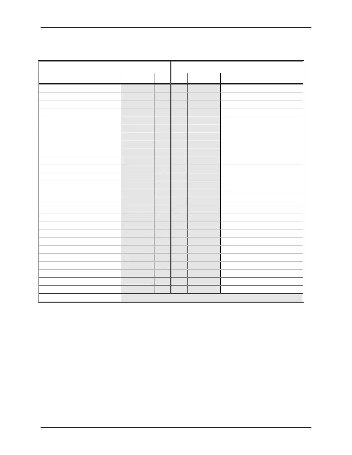
Table 7-1 Rear Terminal Assignments
CONTROLLER BOARD I/O EXPANDER BOARD
Description ID # # ID Description
Power - AC Hot/ DC +
ACH/DC+ H 27 ROUT1nc
Relay Output 1 Normally Closed
Power - AC Neutral/DC -
ACN/DC- N 28 ROUT1c
Relay Output 1 Common
Network Communication A
NCA 3 29 ROUT1no
Relay Output 1 Normally Open
Network Communication B
NCB 4 30 ROUT2nc
Relay Output 2 Normally Closed
Transmitter Power 26Vdc +
XMTR+ 5 31 ROUT2c
Relay Output 2 Common
Transmitter/Station Common
COM 6 32 ROUT2no
Relay Output 2 Normally Open
Transmitter Power 26Vdc +
XMTR+ 7 33 AOUT3+
Analog Output 3 +
Digital Output 1 +
DOUT1+ 8 34 AOUTC
Analog Output 3 Common
Digital Outputs 1/2 Common
DOUTC 9 35 DINU1+
Digital Input Universal 1 +
Digital Output 2 +
DOUT2+ 10 36 DINU1-
Digital Input Universal 1 -
Digital Input 1 +
DIN1+ 11 37 DINU2+
Digital Input Universal 2 +
Digital Input 1 -
DIN1- 12 38 DINU2-
Digital Input Universal 2 -
Digital Input 2 +
DIN2+ 13 39 XMTR+
Transmitter Power 26Vdc +
Digital Input 2 -
DIN2- 14 40 COM
Transmitter/Station Common
Digital Input 3 +
DIN3+ 15 41 AIN4+
Analog Input 4 +
Digital Input 3 -
DIN3- 16 42 AINC
Analog Input Common
Analog Output 1 +
AOUT1+ 17 43 DIN4+
Digital Input 4 +
Analog Output 1/2 Common
AOUTC 18 44 DIN4-
Digital Input 4 -
Analog Output 2 +
AOUT2+ 19 45 AINU1a
Analog Input Universal 1 a
Analog Input 1 +
AIN1+ 20 46 AINU1b
Analog Input Universal 1 b
Analog Input 1/2 Common
AINC 21 47 AINU1c
Analog Input Universal 1 c
Analog Input 2 +
AIN2+ 22 48 AINU1d
Analog Input Universal 1 d
Analog Input 3 +
AIN3+ 23 49 AINU2a
Analog Input Universal 2 a
Analog Input 3 Common
AINC 24 50 AINU2b
Analog Input Universal 2 b
Not Used
IOA 25 51 AINU2c
Analog Input Universal 2 c
Not Used
IOB 26 52 AINU2d
Analog Input Universal 2 d
Ethernet Separate RJ-45 Connector
Notes:
.
1. Safety/Case Ground - Wire to green screw at top center of rear terminal area.
2. Ground Bus - An external, user-supplied ground bus can ease connection of multiple grounds, particularly
when twinaxial cable shields are to be grounded.
3. Terminals 6, 9, 18, 21, 24, 34, 40 and 42 are electrically connected. Use the terminals that allow the best wire
routing and the least stress on components, such as range resistors.

 Loading...


