Installation UM353-1B
April 2012
7-10
7.4.2 Analog Signal Input Wiring (4-20 mA, 1-5 Vdc, and mV)
Siemens 353 analog signal input terminals are connected to software function blocks AIN and AINU within the
controller. Table 7-1 correlates function blocks and input terminals. These terminals will accept several input
signal types with the appropriate wiring and components. A 4-20 current input signal to an AIN function block
must be converted to 1-5 Vdc signal and a 4-20 current input signal to an AINU function block must be converted
to a 15-75 mVdc signal.
INPUT TYPE FUNCTION BLOCKS
(1)
RANGE RESISTOR
(2)
FIGURE(S)
AIN1, 2, 3 and 4
250Ω
7-6 and 7-7
4-20 mA
AINU1 and AINU2
3.75Ω
7-8A
1-5 Vdc AIN1, 2, 3 and 4 Not Required 7-6 and 7-7
Millivolt AINU1 and AINU2 Not Required 7-8B
Notes:
(1) Function blocks AIN4, AINU1, and AINU2 are available only when an I/O Expander Board is
installed.
(2) Range resistors listed are supplied in Installation Kits. For other current values, select a range
resistor that will provide a 1-5 Vdc input. For example, for 10-50 mA, install a 100Ω range
resistor.
Crimp-on connectors are provided for use when a range resistor and a signal input wire are to be inserted in the
same connector terminal. A connector should also be used when two wires of significantly different gauges would
otherwise be inserted in a single connector terminal.
Perform the following steps for each analog input.
1. Select an analog input terminal pair for connection of the input signal wiring. Refer to Table 7-1 and the
following illustrations as necessary.
For a 4-20 mA input, go to step 2. For a 1-5 Vdc or millivolt input, go to step 4.
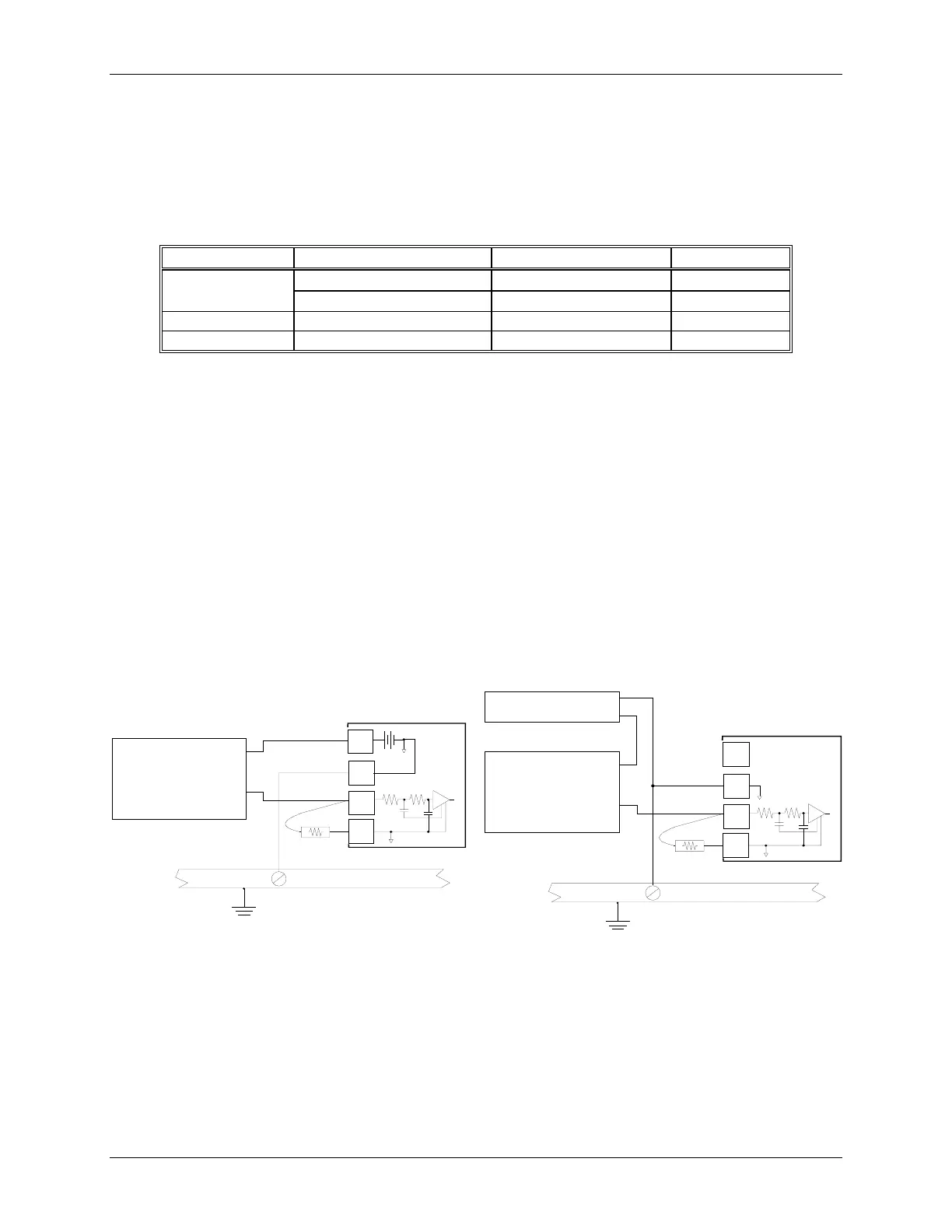
5
20
+
_
Common Ground Bus
Earth
Ground
Model 353
Rear Terminals**
18*
Controller Circuitry
Analog Signal,
e.g. SITRANS P
DSIII, 2-Wire
Transmitter,
4-20 mA Output
+
_
MG00506b
6
250
External Device
1-5 Vdc
26 Vdc
* Or any station common terminal
** See Table 7-1 for AIN2, 3 and 4 terminals
6
20
+
_
Common Ground Bus
Earth
Ground
Model 353
Rear Terminals**
18*
Controller Circuitry
Analog Signal,
e.g. SITRANS P
DSIII, 2-Wire
Transmitter,
4-20 mA Output
MG00507b
250
External Device
1-5 Vdc
+
Station Common
26 Vdc Typical
5
* Or any station common terminal
** See Table 7-1 for AIN2, 3 and 4 terminals
A. Controller Powered
B. External Power Supply
Note: Terminals 6, 9, 18, 21, 24, 34, 40 and 42 are electrically connected. Use the terminals that allow the best wire
routing and least stress on components, such as range resistors.
Figure 7-6 Analog Input AIN1, 2-Wire Transmitter

 Loading...


