UM353-1B Circuit Description
April 2012
12-1
12.0 CIRCUIT DESCRIPTION
This section provides a block diagram level circuit description of the Siemens 353 Controller.
12.1 OVERVIEW
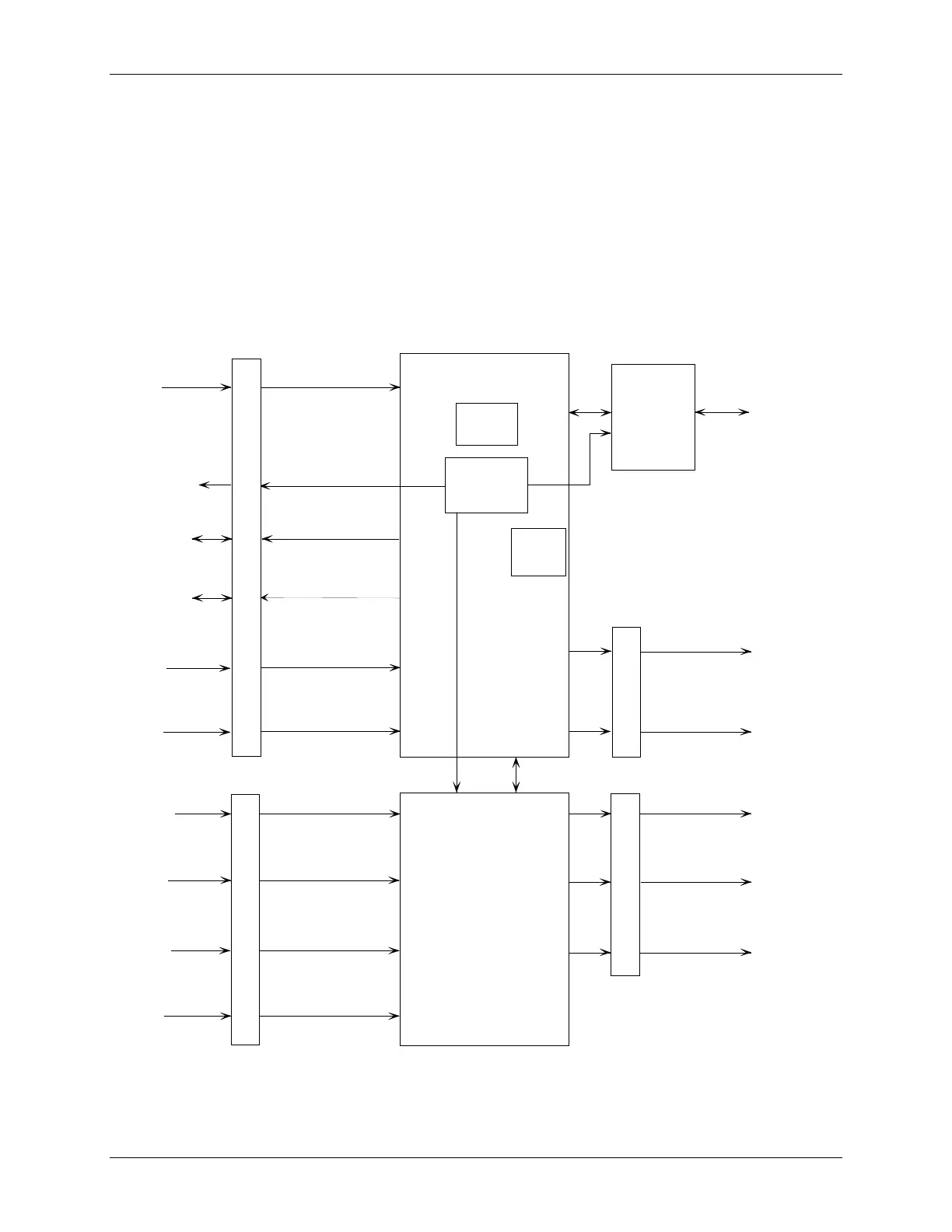
Controller hardware architecture is shown in Figure 12-1. An exploded view of the controller showing individual
assemblies is provided in Figure 1-1.
The Display Assembly is used for operation and configuration. The MPU-based Controller Board performs many of
the controller’s signal processing and process control functions in addition to overseeing internal operations. The
Controller Board’s on-board power supply furnishes DC operating voltages to all plug-in assemblies and to external
process transmitters connected to the rear terminals. The I/O Expander board provides additional I/O. Ethernet
communications is standard.
MPU Controller Board
MPU
Power
Supply
Display
Assembly
with
Operator
Faceplate
RS232
(MMJ-11)
Power
Input
26 Vdc to
Transmitters
Digital
Inputs
1-3
4-20 mA
Analog
Outputs
1 & 2
Digital
Outputs
1 & 2
I/O Expander Board
Universal
Analog
Inputs
1 & 2
Analog
Input 4
Universal
Digital
Inputs
1 & 2
Digital
Input 4
Analog
Inputs
1-3
26 Vdc to
Transmitters
4-20 mA
Analog
Output 3
Relay
Outputs
1 & 2
MG00517a
Rear
Connectors
Rear
Connectors
Modbus
(NCA/NCB)
Ethernet
Network
(RJ-45)
MMC
Socket
Figure 12-1 Siemens 353, Design Level B, Block Diagram

 Loading...


