UM353-1B Installation
April 2012
7-21
G
H
N
Case Rear
Terminals
External Power
120/240 Vac
or 24 Vdc
MG001500
Circuit Breaker
or Fuse
Model 353
White
Black
Green
G
H
= Terminal on rear of case.
= Green ground screw at top center
of rear terminal area.
H = Hot or (+)
N = Neutral or (-)
G = Ground
Earth Ground
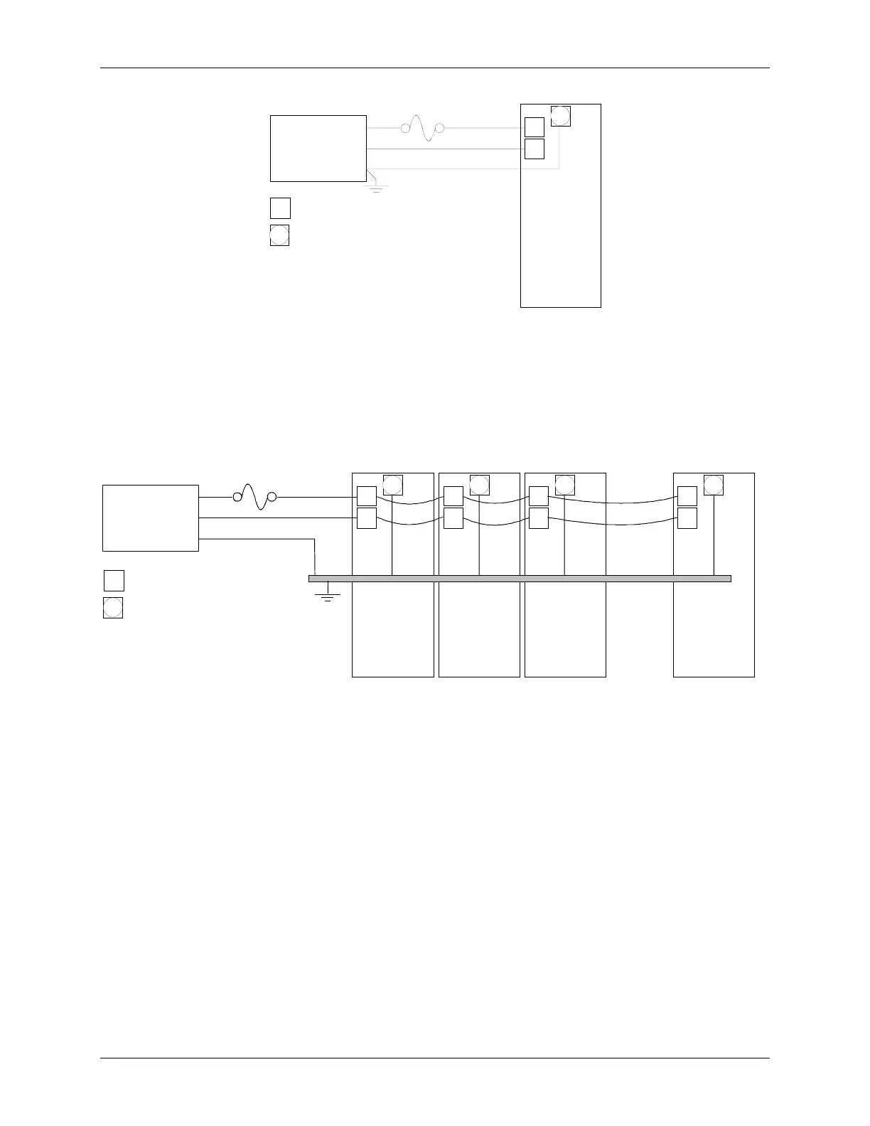
Figure 7-21 Suggested Power Wiring
Where separate wiring is not required, power input wiring can daisy chain together a series of controllers. Here,
each controller, except for the last controller on the daisy chain, will have two wires (18 AWG recommended)
inserted in terminal H and in terminal N. If a larger gauge is to be used, the two wires can be inserted in a crimp-on
connector and the connector inserted in the terminal, for a more secure installation. Daisy chained wiring is shown
in Figure 7-22. Perform the following steps at H, N, and G terminals at each involved controller.
G
H
N
G
H
N
G
H
N
G
H
N
External Power
120/240 Vac
or 24 Vdc
MG00504a
First
Model 353
In The Row
Last
Model 353
In The Row
Circuit Breaker
or Fuse
White
Black
Case Rear
Terminals
G
H
= Terminal on rear of case.
= Green ground screw at top
center of rear terminal area.
H = Hot or (+)
N = Neutral or (-)
G = Ground
Green
Earth Ground
Ground Bus
Figure 7-22 Daisy Chained Power Wiring
1. Strip ground wire(s) 3/8" (10 mm) to 1/2" (13 mm). Clamp the ground wire(s) under the green, square pressure
plate and ground screw (case/safety ground) at top center of each rear terminal area. Tighten the ground screw
to 20 in. lbs.
2. Remove 1/4" (6 mm) to 5/16" (8 mm) from each Hot and Neutral wire to be inserted in a terminal or crimp-on
connector.
3. Crimp-On Connector only - Insert the wires into the crimp-on connector until the wires are visible at the pin
end of the connector. Use a standard electrical connector crimp tool to crimp the connection. Be certain that
both power input wires are fully inserted in the connector before crimping.
4. Loosen the terminal screw using a straight blade screwdriver with a 1/8" (3 mm) blade width.
5. Insert the striped wire or crimp-on connector pin into the terminal and tighten the screw to 5 in. lbs.

 Loading...


