UM353-1B Introduction
April 2012 1-9
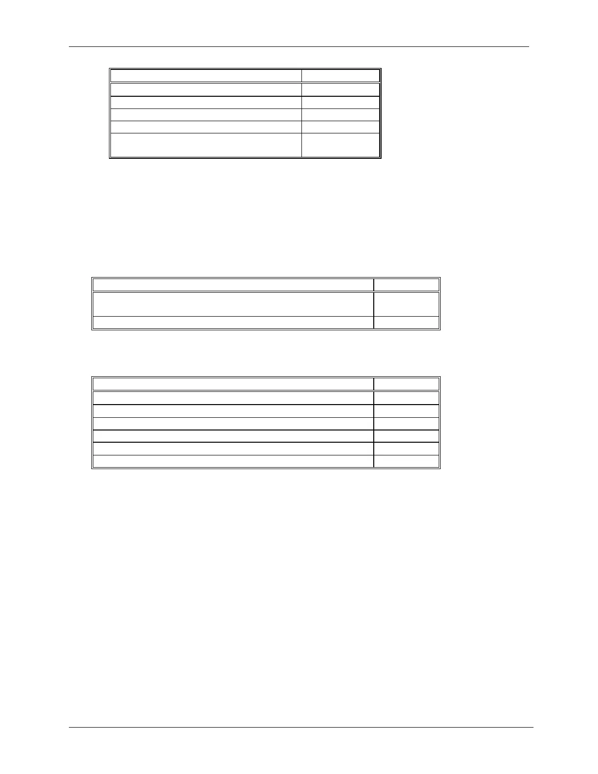
DESCRIPTION QUANTITY
Resistor, 250Ω, 0.1%, 3W, WW
3
Sleeving 3
Crimp-On Connector 6
Kit Installation Instruction 1
Shunt (Not used in Design Level B
controller)
1
4. Mounting Clip Kit, no part number, qty. 1. Kit contains 2, Mounting Clips and 2, 8-32 x 1 Screws (see the Parts
List at back of this manual for part numbers)
5. I/O Expander Board Kits
PN16353-52 I/O Expander Board Kit - The I/O Expander Board is factory installed when a Siemens 353 with
Expansion Board option 1 is ordered.
• For field installation of this kit, see the supplied Kit Installation Instruction (15900-390).
DESCRIPTION QUANTITY
I/O Expander Board - Do not remove Board from static shielding
bag until it is to be installed.
1
Range Resistor and Reference Junction Kit, see below 1
PN16353-49 Range Resistor and Reference Junction Kit - This kit is supplied with the above I/O Expander
Board Kit and with a factory shipped Siemens 353 with Expansion Board option 1.
DESCRIPTION QUANTITY
4-20 mA to 1-5V Range Resistor, 250Ω, 0.1%, 3W, WW
1
4-20 mA to 15-75 mV Range Resistor, 3.75Ω, 0.1%, 3W, WW
2
Sleeving 5
Crimp-On Connector 6
TC Reference Junction, 100Ω
2
Kit Installation Instruction 1
6. Process Instrumentation User Manual CD ROM, qty. 1
7. Installation Guide IG353-1
8. Two warning labels that are to be placed in a highly visible location near the case rear terminals.
9. Additional items as required by your order. Refer to the packing list accompanying a shipment.

 Loading...


