UM353-1B Function Blocks
April 2012
3-55
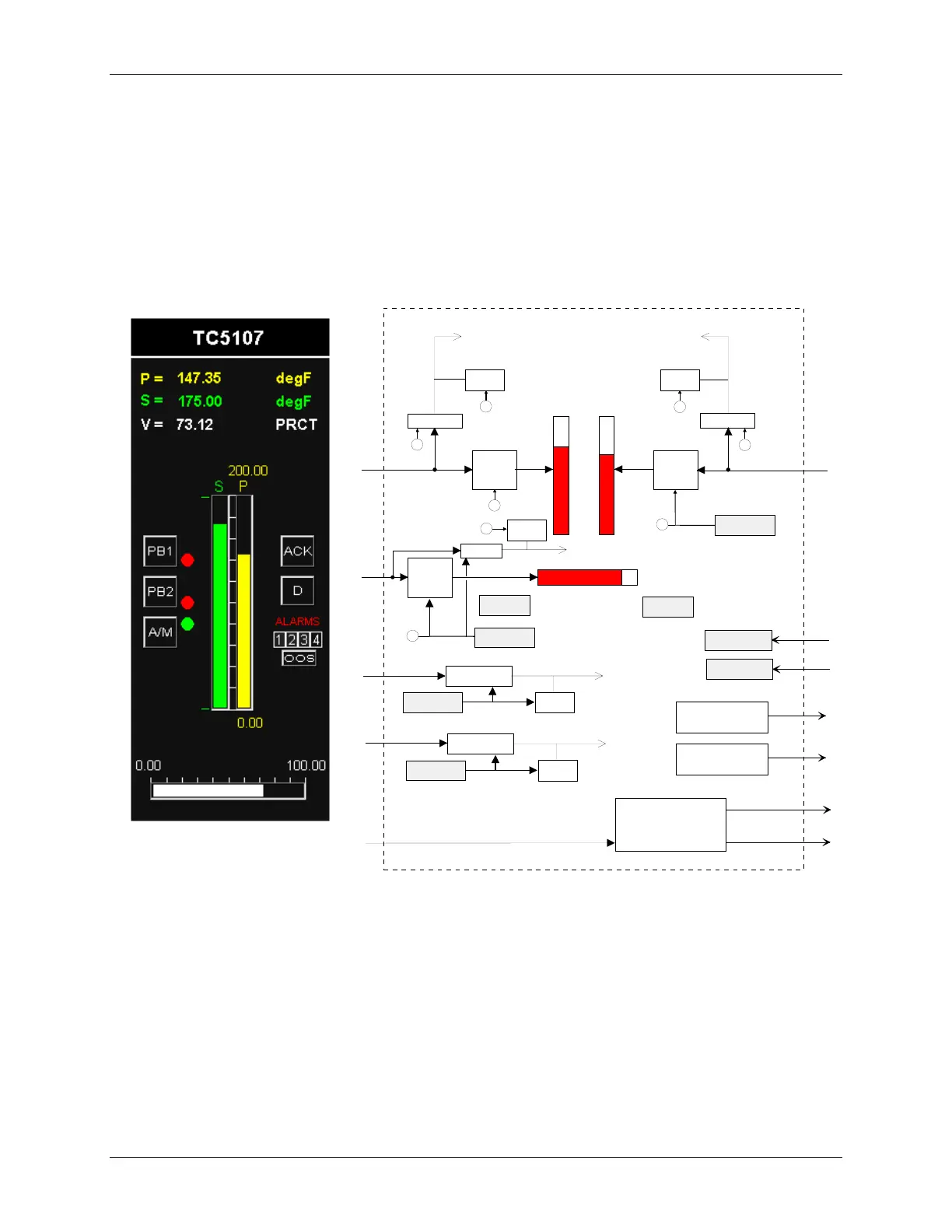
on input CL or from a network command. The Computer CM state can be set high using a network command. The
NL output will normally be connected to the MD input of pushbutton block PB1SW to indicate the C/L switch
position on the operator faceplate, a green LED for C and a red LED for LO.
Output WD will go high (1) when the controller fails to receive a command within the watchdog time. The
watchdog time is set in the STATN (Station Parameters) function block. Input A can be used to acknowledge all the
alarms in all of the loops in a controller. Output PN (Pulse oN) will go high for 0.5 seconds (or one scan cycle
whichever is longer) whenever the bargraph flashes. Bargraph flashing is controlled by the priority setting of
alarms or events. Output PF (Pulse ofF) will go high for 0.5 sec when the flashing bargraph is stopped (e.g.
pressing the ACK button).
P
BLOCK DIAGRAM
IN
put units
E
ngineering
scaling
V
alve
DPP
4
2
3.
4
5
TC 0
5
3
.
P
2
P
rocess
IN
put units
E
ngineering
scaling
P
rocess
P
rocess
DPP
S
S
P
.S
.P
IN
put units
E
ngineering
scaling
V
alve
V
.V
UNITS
P
rocess
UNITS
P
rocess
Input
X _ DPP
X
.Y
Input
Y _ DPP
Y
U
ser
1 STATUS
U1
U
ser
2 STATUS
U2
UNITS
Input
Y
.X
UNITS
Input
X
Alarm Bargraph Flasher
P
ulse o
N
P
ulse of
F
PN
PF
S
tation
E
rror Handling
SE
P
rocess
R
an
G
e
P
oin
T
e
R
UNITS
V
alve
V
alve
R
an
G
e
P
oin
T
e
R
P
rocess
DPP
2
P
P
P
P
V
V
Input
X
R
an
G
e
P
oin
T
e
R
H BAR LD
H BAR RD
CLOSE
OPEN
.
.
P
P
Input
Y
R
an
G
e
P
oin
T
e
R
L
oop
E
vent Handling
LE
Rev. 3
A
Global Alarm Acknowledge
i|ware PC Faceplate Display
 Loading...


