UM353-1B Function Blocks
April 2012
3-61
An operator display must be configured in order to properly map station loop data to network data. Sequencer loop
network data is mapped onto registers or coils
Input CL controls local arbitration of changes to loop data from the network. When input CL is not configured, the
three status outputs LO, CN, and CM will be set high (1) and changes can be made from a network command or the
local faceplate. When CL is configured, it can be toggled locally from a pushbutton switch, such as PB1SW (output
PS), and will change from local to console or from console/computer to local each time the input is toggled. Also,
when output LO goes high, output CN will also go high and CM will go low, indicating that the control source will
change to Console whenever Local is disabled, either by toggling input CL or from a network command. The
Computer CM state can be set high using a network command. The NL output will normally be connected to the
MD input of the pushbutton block PB1SW to indicate the C/L switch position on the operator faceplate using the
green LED for C and the red LED for LO.
Output WD will go high (1) when the station fails to receive a Modbus network command within the watchdog
period. The watchdog time is set in the STATN (Station Parameters) function block.
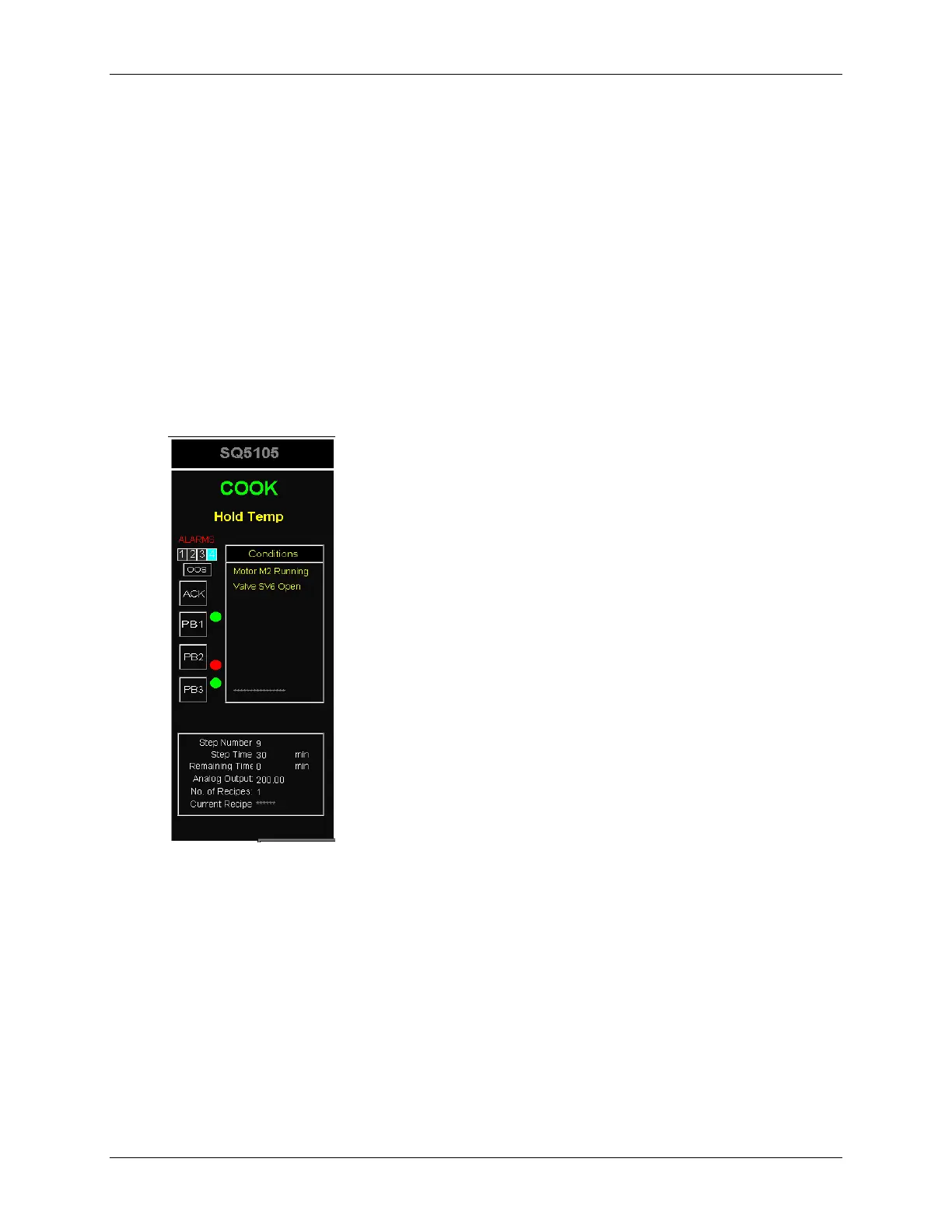
i|ware PC Faceplate Display
 Loading...


