3 Description
3.2 Circuit-Breaker
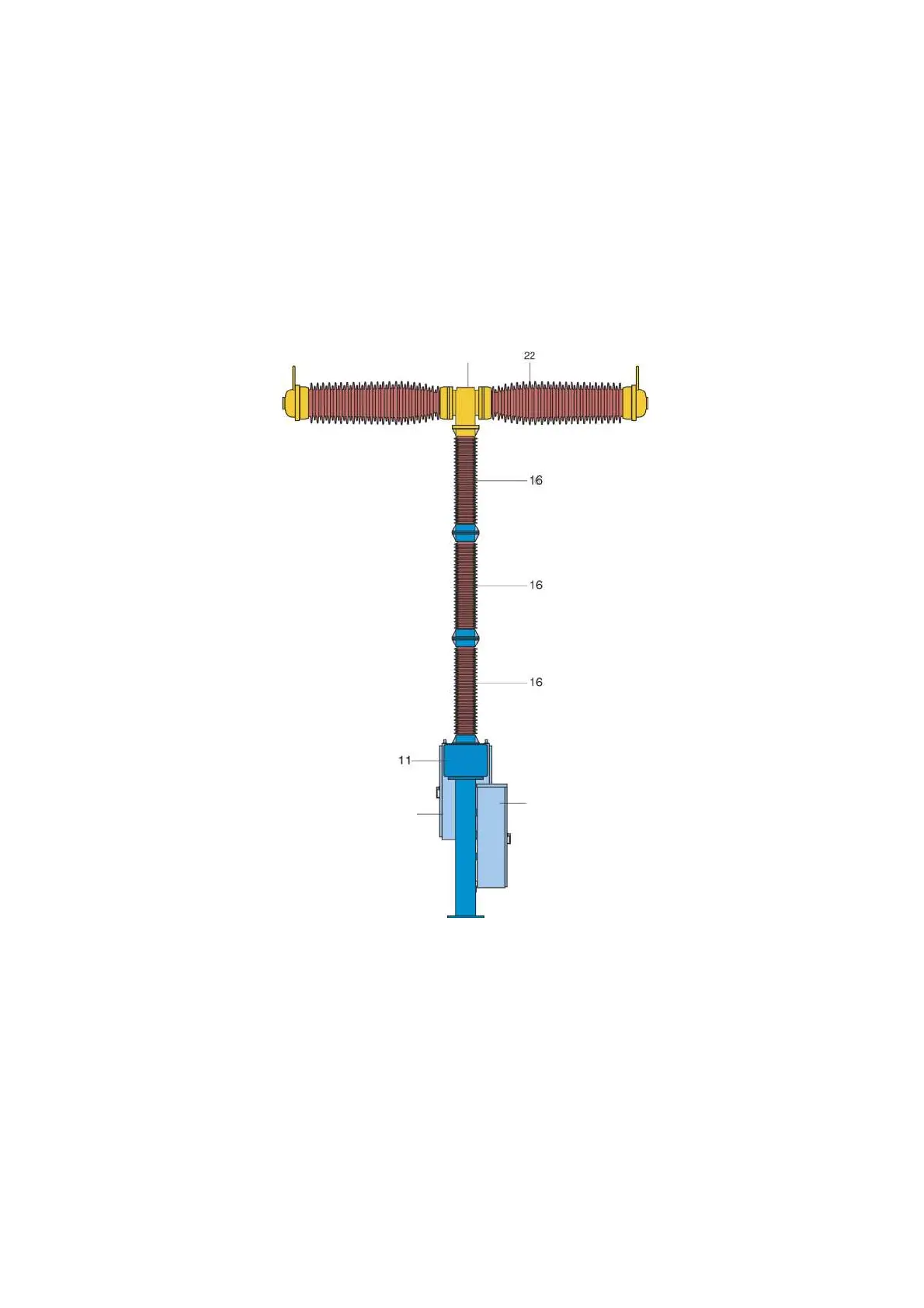
The pole columns of the circuit-breaker are each mounted on a base 11, to the side of each of which an operating
mechanism cubicle 15.1 is fitted.
The insulator columns are assembled from several multished insulators and each of them supports an double
break interrupter assembly consisting of two interrupter units 22 with grading capacitors 23 connected in parallel
and a bell-crank mechanism 21.
Control cabinet 12 is also located at pole B.
15.1
12
21
11 Base
12 Control cubicle
15.1 Operating mechanism cubicle
16 Post insulator
21 Bell-crank mechanism
22 Interrupter unit
Fig. 2 Design of the circuit-breaker 3AP2 Fl
1003000a
13