4 Installation
53
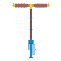
11.13 Pillar
12 Control cubicle
Fig. 31 Assemble control cubicle at pillar
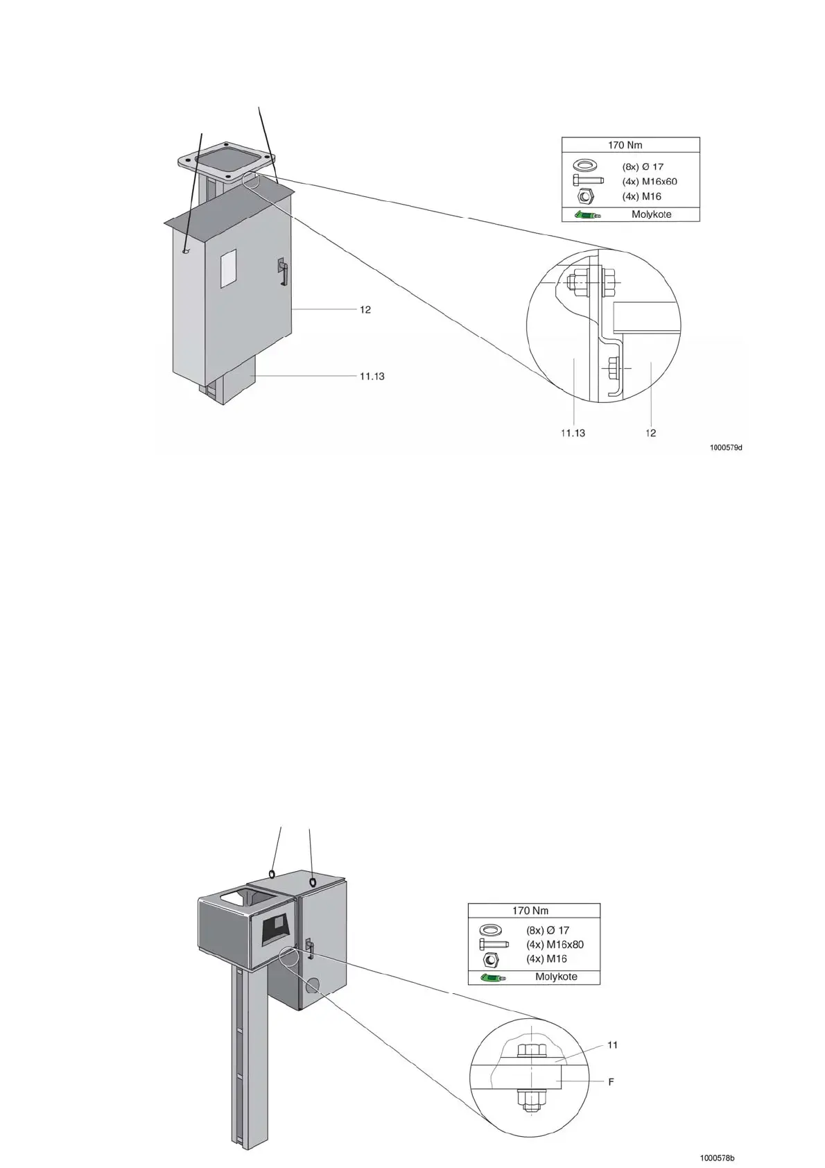
4.5.6 Assembly of the Operating Mechanism
Cubicles
The doors of the operating mechanism cubicles are labelled LA, LB and LC. The operating mechanism cubicles
are assembled on the pillars for poles A, B and C according to this labelling.
This allocation of operating mechanism to poles must be strictly observed because of the coded pole connecting
cables.
To assemble the drive cabinet, insert the crane hooks into the lifting eye-bolts of the drive cabinet and undo the
screwed connections to the other components of the transport unit.
Place the operating mechanism cabinet with base 11 onto flange plate F of the corresponding pillar and secure
with screws (4 screws M 16x80, 4 nuts, 8 washers from the accessory pack).
The length of the bolts from the accessories pack is suitable for a pillar wall thickness of up to 45 mm
(Fig. 32).
4
4 Installation