3 Description
3.4 Interrupter Unit
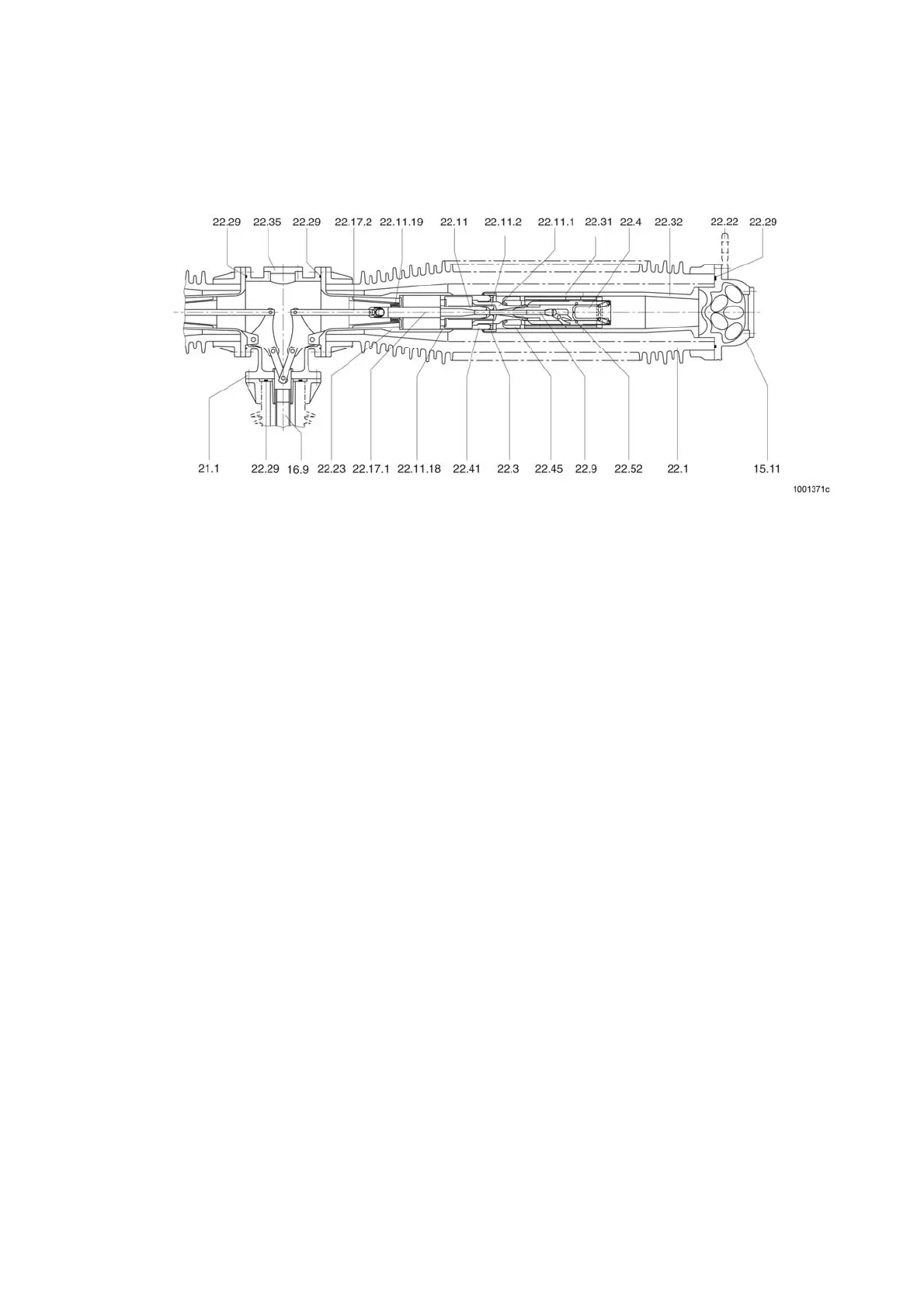
Fig. 5 shows a sectional view of an interrupter unit. The breaker contacts are accommodated in the gas-tight
porcelain jacket 22.1.
15.11 Filter cowl
16.9 Operating rod
21.1 Gear unit housing
22.1 Jacket
22.11 Tube contact
22.11.1 Nozzle
22.11.17 Piston
22.11.18 Valve plate
22.11.19 Valve group
22.11.2 Auxiliary nozzle
22.17.1 Pull rod
22.17.2 Coupling rod
22.22 High-voltage terminal
22.23 Inner socket
22.29 Sealing ring
22.3 Contact laminations
22.31 Contact carrier
22.32 Base
22.35 Cover
22.4 Tandem gear
22.41 Heat cylinder
22.45 Electrode
22.5 Guide rail
22.52 Pin
22.9 Pin
Fig. 5 Interrupter unit
The main circuit of an interrupter unit consists of the high-voltage terminal 22.22, the socket 22.32, the contact
carrier 22.31, the contact laminations 22.3 arranged in rings in the contact carrier, the heat cylinder 22.41, the
inner socket 22.23 and the gearbox 21.1.
The contact laminations 22.3 support themselves centrically from the contact carrier 22.31 inwards to the heating
cylinder 22.41. The internal stress of the contact laminations 22.3 generates the necessary contact pressure from
the contact carrier 22.31 onto the heating cylinder 22.41.
17