4 Installation
W350 Spacer
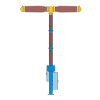
16.3 Post insulator
16.6 Centering guide
16.6.1 Teflon strip
16.7 Sealing ring
16.9 Operating rod
16.9.1 Yoke head
21.1 Housing
21.7 Coupling lever
21.7.3 Bolt
Fig. 46 Centering guide and coupters fitted
Attention
Hold the double-break assembly by means of the crane; do not lift it!
Remove the three spacers. To do this, unscrew the nuts and unscrew the threaded bolt downwards out of the
hexagonal socket. Remove the hexagonal socket to the side.
Before the double interrupter head is lowered, release the reversing lever 15.9 from its locked position -remove
the rubber retaining ring and bolt 10.9.
Carefully lower the double interrupter head onto the insulator and screw it onto the insulator column to 170 Nm
with 8 screws M 16x75.
4.5.9 Lifting Plate
The lifting plates used for hoisting the double interrupter head are removed. The screws are re-used.
64