4 Installation
Remove the transport cover 21.9.9 (Fig. 45) from the double interrupter head and take out the desiccant bags.
Prepare the sealing flanges as described above.
Remove the cable binder used as transport protection. Bring the interrupter unit into OPEN position by pulling the
two coupling levers jerkily as far as they will go. The coupling bolt 21.7.3 supplied can be used for this purpose.
The double interrupter head is placed on the spacer in such a way that the grading capacitors are situated on the
side of the operating mechanism cabinet.
The holes in the fork head of the drive rod and in the two coupling levers should be aligned, to enable the
coupling bolt to be inserted. To do this, the two coupling levers are held in a V-shape with one hand, while the
coupling bolt is inserted into the aligned holes with the other hand after positioning the drive rod.
Protect coupling bolt 21.7.3 with PE fuse 21.11.
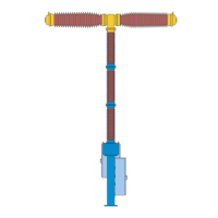
1002230a
VD Packaging cap
15.16.3 Desiccant agent
1.8 Lifting eye-bolt
21.9.9 Packaging cap for double interrupter head
Fig. 44 Packaging cap for double interrupter head and insulator column
62