7PG21 Solkor Rf Commissioning
©2012 Siemens Protection Devices Limited Chapter 6 Page 20 of 21
4.3 Commissioning
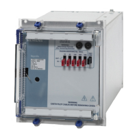
This publication gives details of the tests necessary to prove that the Solkor Rf injection intertripping equipment
using a type TEC relay and a D.C./ A.C. inverter has been installed and is operating correctly.
For connections of the equipment reference should be made to the appropriate schematic diagram. Tests of the
Solkor Rf protection should be done separately as detailed in leaflet OR/R.
4.3.1 Description of operation of TEC relay
Operation of the intertrip send initiating contact causes the multi-contact, electrically reset type F element to
operate and this immediately open circuits the pilots on the local-end relay side and connects the injection supply
across the pilots. The contacts on the pilot side are insulated to withstand a voltage of 5kV or 15kV to earth.
At the same time a type B relay element is energised and after 100 milli-seconds a contact on this relay isolates
the operate the operate coil circuit of the multi-contact type F element.
After 2 seconds a type TCD timing relay which is energised from a contact on the type F element resets the type
F element thus disconnecting the injection supply.
A two second intertrip pulse is therefore given irrespective of whether the initiating contact is self or hand reset. If
the initiating contact is self reset the TEC relay resets completely but if it is hand reset the type B element remains
energised until the Initiating contact is reset.
4.3.2 Check on D.C/ A.C. inverter
Remove external connections from inverter terminals A1, A3.
Connect a 20 watt 2000 ohm resistor across terminals A1 and A3. Arrange the test circuit as shown in Fig.12.
Measure the, input voltage and the voltage across the 2000 ohm resistor.
Check that the output voltage across the 2000 ohm resistor is within the limits shown in Fig 11.
Check that the input current does not exceed 2 amps D.C.
Fig 11. DC/AC Inverter (Art.No. 410A21535)

 Loading...


