11
Mounting the RMD (if equipped)
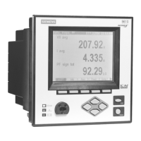
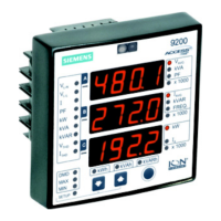
The Remote Modular Display (RMD) is a product option for 9200 TRAN
meters. The RMD can be mounted in either a standard DIN or ANSI cutout.
See the
9200 RMD Retrofit Instructions
for more information.
Remote Modular Display Connections
NOTE
Only use the supplied cable to connect the RMD.
Step 3: Wire the Ground Terminal
Wire the meter’s ground terminal to the switchgear earth ground using a
14 AWG (2.1mm
2
) or larger wire.
Connect the power supply G (ground) terminal to the same point as the meter
terminal.
CAUTION
Do not use metal door hinges as a ground path.
Step 4: Wire the Digital Outputs (if equipped)
Two optional Form A digital relays can be used for energy pulsing and/or
control applications.
Digital Output Connections
Connector Type RJ11
Wire 26 gauge 6 conductor cable
Connector Type Captured wire
Wire
24 AWG to 18 AWG wire
(0.08 mm
2
to 0.82 mm
2
)
Maximum Forward Current 150 mA
Maximum Voltage 200 VDC/VAC
Maximum Current 150 mA
Isolation Optical
 Loading...