Do you have a question about the Siemens 9200 and is the answer not in the manual?
General information disclaimer, user responsibility for safe practices, and right to change.
Defines personnel qualified to install and operate the equipment based on training and authorization.
States instructions do not cover all details and refers to sales office for further information.
Covers DANGER and CAUTION notices related to installation safety and potential hazards.
Includes FCC notice, network compatibility, and standards compliance information.
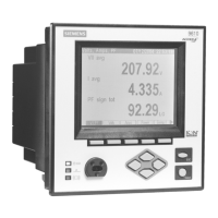
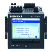
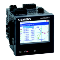
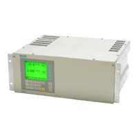
Describes Integrated Display, TRAN (transducer), and RMICAN models.
Details various hardware and software options available for the 9200 meter.
Outlines preliminary steps including reading safety precautions and verifying parts.
Lists combinations of Options Codes and their corresponding part number suffixes and descriptions.
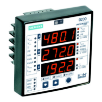
Describes the front panel components and displays of the 9200 meter.
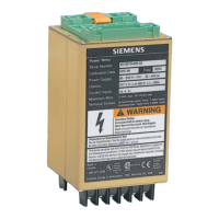
Details the rear panel connections and terminals of the 9200 meter.
Provides dimensional drawings for the Integrated model of the 9200 Power Meter.
Provides dimensional drawings for the TRAN model of the 9200 Power Meter.
Provides dimensional drawings for the Remote Modular Display (RMD) unit.
Advises on troubleshooting if the display shows zero frequency due to incorrect Options Card insertion.
Lists the operating and storage temperature and humidity ranges for the meter.
Details mounting the Integrated model using ANSI 4" and DIN 96 standards.
Describes flush and DIN rail mounting methods for the TRAN model.
Details mounting the Remote Modular Display (RMD) unit.
Covers wiring the ground terminal and optional digital outputs.
Lists technical specifications for voltage inputs, including connector type, wire, ratings, and compliance.
Explains when PTs are required and their specifications for meter input compatibility.
Specifies compliance and rating requirements for current transformers (CTs) used with the meter.
Illustrates direct connection for 4-wire Wye systems with 3 elements.
Illustrates connection for 4-wire Wye systems using 3 PTs and 3 CTs.
Illustrates connection for 4-wire Wye systems using 2 PTs and 3 CTs.
Illustrates connection for 3-wire Delta systems using 2 PTs and 3 CTs.
Illustrates connection for 3-wire Delta systems using 2 PTs and 2 CTs.
Illustrates direct connection for 3-wire Delta systems.
Illustrates direct connection for 3-wire grounded Wye systems with 3 elements.
Illustrates the connection diagram for single-phase power systems.
Details RS-485 COM1 port specifications, cable, and available protocols.
Lists power supply options, rated inputs, and specifications for connecting the power supply.
Illustrates wiring diagrams for different power supply types.
Steps for powering up the meter and configuring it using the front panel.
Configuration for Volts Mode, Potential Transformer (PT) and Current Transformer (CT) ratios.
Settings for polarity, demand intervals/periods, and communication parameters.
Configuration for Modbus scaling and digital output modes/time constants.
Settings for display behavior and password protection.
Instructions to verify power reception and meaningful display values for Integrated/RMD models.
Instructions to verify power and LED flashing rate for TRAN models without RMD.
Explains how to view parameter measurements in the default display mode.
Lists parameters measured in Display Mode for different meter models and packages.
Explains how to interpret the "x 1000" indicator for actual value scaling.
Details button operations for selecting and editing parameters in configuration mode.
Explains the password requirement for initial parameter configuration.
Information on software and how to use Information Mode to view meter details.
Describes the initial LED and display test upon entering Information Mode.
Lists measurements available with the standard package.
Lists measurements available with Enhanced Package 1 and 2.
| Brand | Siemens |
|---|---|
| Model | 9200 |
| Category | Measuring Instruments |
| Language | English |