EasyManua.ls Logo

Siemens 9610 User Manual

Siemens 9610
28 pages
To Next Page IconTo Next Page
Page #1 background imageLoading...
Page #1 background image
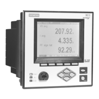
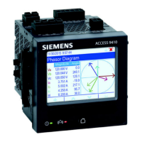
9510 / 9610 Power Meter
Installation Guide
Question and Answer IconNeed help?

Do you have a question about the Siemens 9610 and is the answer not in the manual?

Siemens 9610 Specifications

General IconGeneral
BrandSiemens
Model9610
CategoryMeasuring Instruments
LanguageEnglish

Summary

Important Safety and User Information

DANGER and Warnings

Electrical equipment hazards, safe operation, and qualified personnel requirements.

Installation Considerations

DANGER Statements

Critical safety warnings regarding hazardous voltages and improper use.

Before You Begin and Meter Overview

Safety Precaution Before Installation

Crucial safety warning before powering up the meter.

Mounting and Grounding Instructions

Step 2: Wire the Ground Terminal

Procedure for connecting the meter to earth ground.

Wiring Voltage and Current Inputs

Connection Diagrams: Wye Configurations

4-Wire Wye, 3-Element, Direct Connection

Wiring diagram for a 4-wire Wye, 3-element direct connection.

4-Wire Wye, 3-Element, 3 PTs Connection

Wiring diagram for a 4-wire Wye, 3-element connection with 3 PTs.

4-Wire Wye, 2½-Element, 2 PTs Connection

Wiring diagram for a 4-wire Wye, 2.5-element connection with 2 PTs.

Connection Diagrams: Delta and Wye Configurations

3-Wire Solid-Grounded Wye, 3-Element, Direct Connection

Wiring diagram for a 3-wire solid-grounded Wye, 3-element connection.

3-Wire Delta, 2½-Element, Direct Connection

Wiring diagram for a 3-wire Delta, 2.5-element direct connection.

3-Wire Delta, 2-Element 2 PTs & 2 CTs

Wiring diagram for a 3-wire Delta, 2-element connection with 2 PTs and 2 CTs.

Connection Diagrams and PT Usage

3-Wire Delta, 2½-Element, 2 PTs & 3 CTs

Wiring diagram for a 3-wire Delta, 2.5-element connection with 2 PTs and 3 CTs.

Single Phase Connection Diagram

Wiring diagram for a single-phase connection.

Wiring Communications: RS-232, RS-485, and Infrared

RS-232 Connections (COM1)

Specifications and wiring for RS-232 serial communication.

RS-485 Connections (COM1 and COM2)

Specifications and wiring for RS-485 serial communication.

Wiring Communications: Ethernet and Modem

Ethernet Connections (10Base-T and 10Base-FL)

Wiring and specifications for Ethernet connectivity.

Power Supply, Power Up, and Initial Setup

Step 6: Wire the Power Supply

Instructions for wiring the standard and low voltage DC power supplies.

Step 8: Set Up the Meter Using the Front Panel

Guide to configuring meter settings via the front panel interface.

Front Panel Configuration: Security and Verification

Step 9: Verify Meter Operation

Instructions to verify meter functionality after setup.

Step 10: View Meter Data

Related product manuals