16
Step 5: Wire the Communications
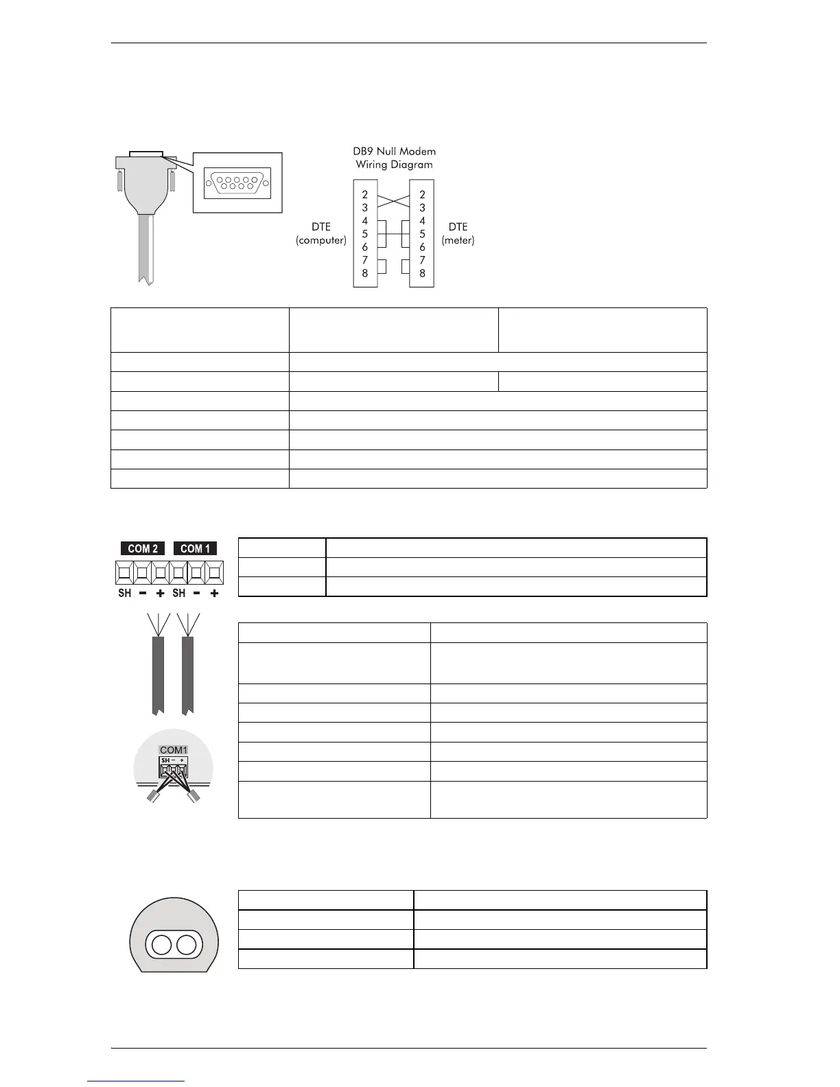
RS-232 Connections (COM1)
RS-485 Connections (COM1 and COM2)
Infrared Connections (COM4)
51
96
Null modem
cable pinout
Pin 3 - Transmit Data - Pin 2
Pin 2 - Receive Data - Pin 3
Pin 7 - Reque
st to Send- Pin 8
Pin 8 - Clear to Send- Pin 7
Pin 5 - Signal Ground- Pin 5
Pin 6 - Data Se
t Ready- Pin 4
Pin 4 - Data Terminal Ready- Pin 6
Specification Meter Connected to Computer
Meter Connected to External
Modem
Connector Type DB9 female end for mating with male connector on the meter
Wire Null modem RS-232 cable Straight-through RS-232 cable
Maximum Cable Length
15.2 m (50 ft)
Data Rate 300 – 115,200 bps
Isolation Optical
Duplex Full
Compliance ANSI/IEEE C37.90-1989 surge withstand and fast transient tests
SH RS-485 Shield (electrically connected to chassis ground)
– RS-485 Data Minus
+ RS-485 Data Plus
Connector Type Captured wire
Wire
Shielded twisted pair RS-485 cable,
22 AWG (0.33 mm
2
) or larger
Maximum Cable Length 1219 m (4000 ft) total for entire bus
Data Rate 300 – 115,200 bps
Maximum Devices (per bus) 32
Isolation Optical
Duplex Half
Compliance
ANSI/IEEE C37.90-1989 surge withstand
and fast transient tests
Connect SH at
one end only
Interface ANSI C12.18 Type II optical port
Location Front of meter
Data Rate 1,200 – 19,200 bps
Duplex Half
 Loading...