005109_b_en−2
7
Fire & Security Products
Siemens Building Technologies Group
07.2004
3 Preparation of hardware
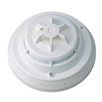
3.1 Control module ’Extinguishing’ E3G080
Pos. Component Preparation Default
1 Programming switch ’S3’: I-Bus address set according to system documentation Address 0
2 Programming switch ’S2’: Determine emer-
gency operation concept
set according to system documentation
S2-1/2 −> ’OFF’ = no function if µP E3G080 malfunctions
. see also description in document 1260
all switches to ’ON’
3 Resistors ’R60/61’ Activating device 1 is between 16 ... 160Ω:
−> Remove ’R60’ (71K5)
Activating device 2 is between 16...160Ω:
−> Remove ’R61’ (71K5)
’R60/61’ inserted
−> for activating device 161....320Ω
4 Maintenance switch ’S1’: Test to block all
outputs, without real activation (activation
test LEDs ’H1’....’H4’)
set to ’ON’, so that when switching on for the first time, all
outputs are blocked (meaning of the LEDs see chapter 4.2)
set to ’OFF’
5 Maintenance switch ’S4’: For initialization
of commissioning functions
only effective if switch ’S1’ is set to ’ON’
. description see chapter 4.2
−
6 Jumper ’X2’: Ground fault monitoring
’LON-Bus’
Ground fault monitoring . see also in document 004594
set as described in document 1260, chapter ’Ground fault
monitoring’
removed (inactive)
7
mP ’D2’
check version, see Release notes docu 004767 inserted
8 Connection level check that all peripheral equipment planned is connected
(according to system documentation)
−
1
X2
R61
R60
3
2
4
R151
S1
S3
S2
S4
6
D2
7
8
5
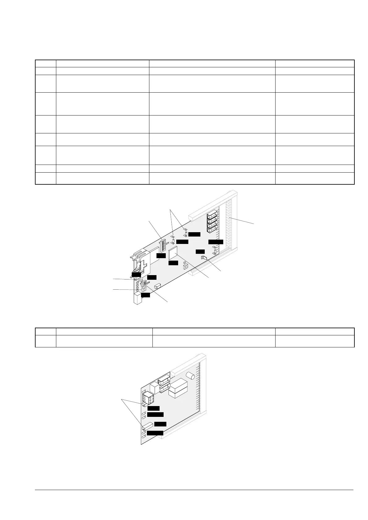
3.2 Dual sector extinguishing p.c.b K5L020
Pos. Component Preparation Default
1 Potentiometer ’R91’/’R92’: Calibration of
control lines
Procedure . see description in document 1260
−
1
R91
R92
LED 3
LED 4
 Loading...