005109_b_en−2
17
Fire & Security Products
Siemens Building Technologies Group
07.2004
8 Error diagnosis
All faults at the inputs/outputs of the E3G080 are individually displayed at the AlgoPilot. For
each of the 4 outputs an LED is provided on the E3G080 for error diagnosis (see chapter 4.2).
Separate LEDs are not provided for the inputs, but a special mode enables the identification of
each faulty or deactivated input and output.
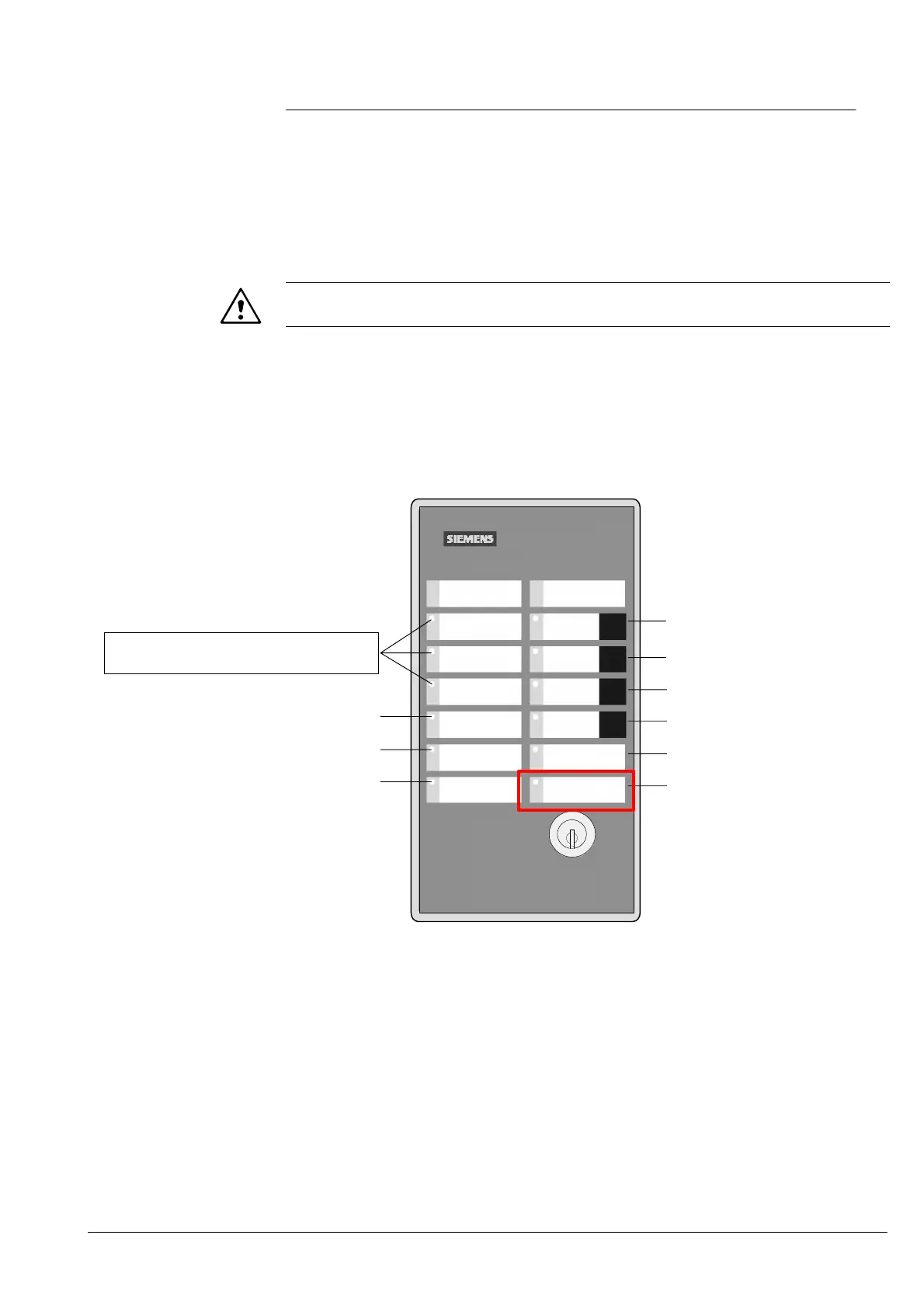
8.1 Fault identification at the operation unit
extinguishing B3Q440
NOTE
Functions only when a fault is pending
Procedure:
1. If fault set switch ’S1’ (E3G080) to ’ON’
2. Press ’S4’ key (E3G080) once
3. LEDs ’Fire detector activated’ / ’Evacuation’ and ’Extinguishing released’ flash simulta-
neously
4. Identify the input/output concerned according to the diagram below
Evacuation
Fire detector
activated
Extinguishing
released
Fault
System ON
Automatic
release
blocked
Autom.+Man.
release
blocked
Switch off
warning
panel
Switch off
sounder
Emergency
stop
Cerberus
B3Q440
Differentiation between open line/short circuit:
− slow flashing = open line
− rapid flashing = short circuit
Line ’Illuminated warning panel’
Line ’Manual activation’
Line ’Stop-/blocking button’
Line ’Extinguishing agent loss’
Line ’Extinguishing blocked’
Line ’Extinguishing released’
Line ’Extinguishing horn’
Line ’Sector valve’
Line ’Main valve’
All 3 LEDs flashing = Operating unit ex-
tinguishing in mode ’Error diagnosis’
Loss of extinguishing
agent
5. Cancelling function: Set switch ’S1’ to ’OFF’
 Loading...