005109_b_en−2
10
Fire & Security Products
Siemens Building Technologies Group
07.2004
4.2 Automatic calibration
System power up
1. Press ’S4’ key once (service switch ’S1’ must be in position ON)
Ü Situation A:
When all in−/outputs are in order, or when there is no change to the configuration, or when
the monitoring has been deactivated, all LEDs ’H1’...’H4’ are flashing simultaneously du-
ring approx. 5 seconds; afterwards the deactivated control lines are briefly displayed in
sequence in short time intervals (see table below). The initialisation (calibration) is comple-
ted; proceed to step 5.
Ü Situation B:
When in−/outputs are faulty, or when the configuration has been changed, the LEDs
’H1’/’H3’ and ’H2’/’H4’ are flashing alternately during approx. 5 seconds, then the faulty
and deactivated control lines are briefly displayed in sequence in short time intervals
(see table below).
2. Remedy fault and/or change configuration
3. Press service key ’S4’ once to read in the new situation
Ü the LEDs react in accordance with situation B
4. Press service key ’S4’ once to acknowledge the new situation
Ü the LEDs react in accordance with situation A
5. Set service switch ’S1’ to OFF
Ü The extinguishing activation is ready for operation.
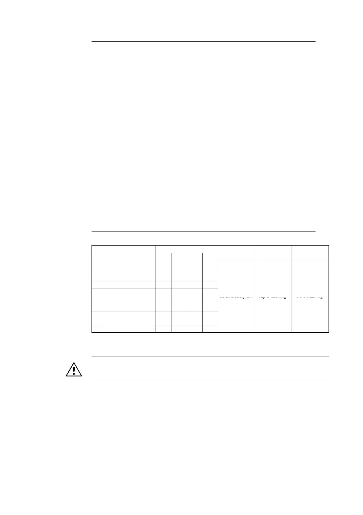
4.2.1 Status indication on E3G080
Note: Each pending fault signal is visible approx. 4 sec. (sequential display)
Function In-/Output
LED
De-activated Short circuit Open line
’H1’ ’H2’ ’H3’ ’H4’
Sector valve delayed
l
Main valve non-delayed
l
Horn
l l
Illuminated warning panel
l
Manual actuation
(spec. button yellow)
l l
continuously on rapid flashing slow flashing
Emergency stop-/
Blocking key
l l
Loss of extinguishing agent
l l l
Extinguishing blocked
l
Extinguishing released
l l
The LEDs marked by black spots stand for the in−/output concerned;
e.g. control line Extinguishing released -> LED ’H1’ + ’H4’ flash or light up simultaneously
Important
When an extinguishing command has missed prior to the calibration and has been reported
as faulty, this fault is deleted afterwards.
 Loading...