005109_b_en−2
8
Fire & Security Products
Siemens Building Technologies Group
07.2004
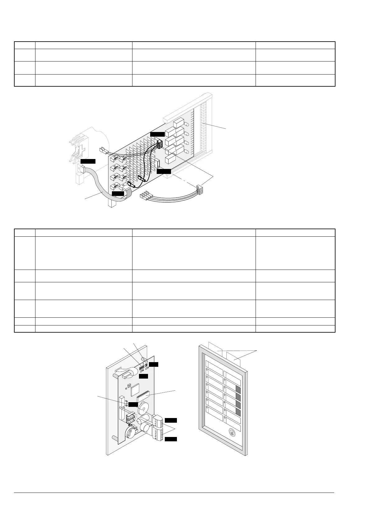
3.3 Emergency operation link E3G110
Pos. Component Preparation Default
1 Distributor cable: Line links of the extinguis-
hing sections
to connect and to shunt according to system documenta-
tion
not inserted (contained in module)
2 Flat cable F12A100/F12A470: Connection to
line module connector ’ST10’
connect according to system documentation
. Details see also description in document 1260
order separately
3 Connection level check that all peripheral equipment planned is connected
(according to the system documentation)
−
1
ST11
ST12
ST1
ST10
2
3
3.4 Operating unit ’Extinguishing’ B3Q440
Pos. Component Preparation Default
1 Inscription strips insert not insert
−> delivered with strips in ’english’
for operating unit ’extinguishing
B3Q440 and AlgoPilot, or to be
created with Word template DOT
(document 006516)
2 Programming switch ’S3’: Equipment ad-
dress
set according to system documentation Address 1 (’OFF’)
3 Programming switch ’S2’: Key click, Buzzer set according to system documentation
’S2-1’ −> ’ON’ = Key click active
’S2-2’ −> ’ON’ = Buzzer active
set to ’OFF’
4 Resistor ’R2’: Line termination for the com-
munication to E3G080
set according to system documentation, is not the last
device, remove resistor ’R2’, see description in document
1260 −> E3G080
inserted
5 EPROM ’D1’ check version, see Release notes docu 004767 inserted
6 Plug-in terminals ’ST1’ / ’ST2’ connect according to system documentation supplied with B3Q440
2
S3
1
2
3
S2
R2
ST2
ST1
4
6
5
 Loading...