7HVWLQJ)XQFWLRQV'LDJQRVWLFVDQG)DXOW(OLPLQDWLRQ
S7-300 Automation System, Hardware and Installation: CPU 31xC and CPU 31x
A5E00105492-03
11-27
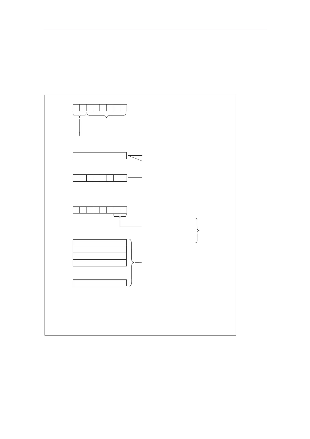
,QWHUUXSWVWDWXV
The interrupt status of module diagnostics provides details on a DP slave. The
maximum length of module diagnostics starting at byte y is 20 bytes.
The following figure describes the structure and content of the bytes for a
configured address area of intermediate memory.
Byte y +1
01H: Code for diagnostics interrupt
Byte y +4
to
Byte y +7
Byte y
Length of the device-related diagnostics incl. byte y
(max. 20 bytes)
Code for device-related diagnostics
Byte y +3
Slot No.
2 = CPU
4...35 = No. of the configured address area
00 = No additional information
on diagnostic status
01 = Incoming diagnostics
10 = Outgoing diagnostics
11 = Outgoing diagnostics,
but there are still
disturbances
(there is at least 1 error)
Byte z
7 654 3210 Bit No.
00
7 6 5 4 3 2 1 0 Bit No.
Example on byte y+2
CPU = 02H
1. Address area = 04H
2. Address area = 05H
Byte y +2
000
0
00
Diagnostics or interrupt data
.
.
.
Only for
diagnostic
interrupt
02H: Code for process interrupt
of the intermediate memory
etc.
Figure 11-9 Structure of the interrupt status
 Loading...