q
Input selection
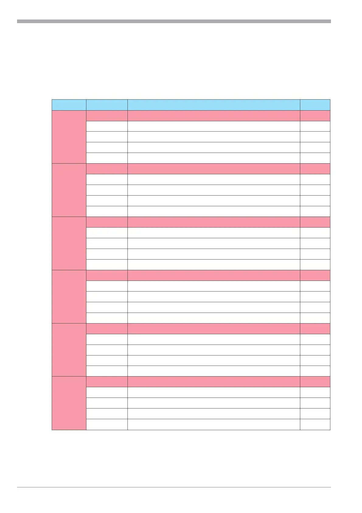
For configuration menu LOGI additional menus for selecting typical digital
inputs for tempering equipment are available.
LOGI
Name Range Description Default
StB Source for safety temperature limiter signal 0
0 interface only
2 di1 switches
3 di2 switches
4 di3 switches
L.Sta Source for local function start 0
0 interface only
2 di1 switches
3 di2 switches
4 di3 switches
L.Sto Source for local function stop 0
0 interface only
2 di1 switches
3 di2 switches
4 di3 switches
SEnS Source for sensor operating mode (internal, external) 0
0 interface only
2 di1 switches
3 di2 switches
4 di3 switches
LEvL Source for level alarm 0
0 interface only
2 di1 switches
3 di2 switches
4 di3 switches
Flo Source for flow alarm 0
0 interface only
2 di1 switches
3 di2 switches
4 di3 switches
Configuration extensions
12 Operating note KS 50-1 TCont
 Loading...