2 Hints on operation
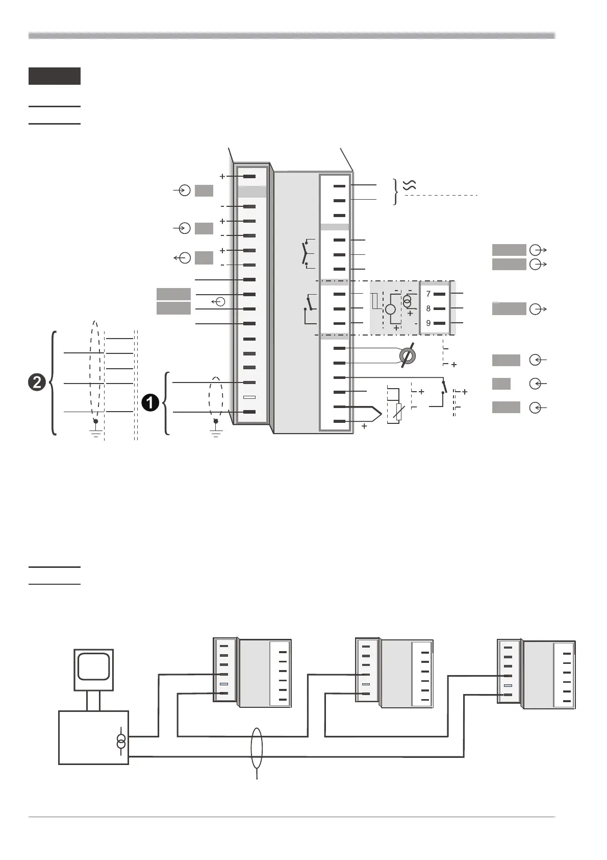
2.1 Electrical connections
* Safety switch mA i V turned left
g
The controller is provided with flat-pin terminals 1 x 6,3mm or 2 x 2,8mm to
DIN 46 244. Or with screw terminals depending on ordering code.
2.2 Bus interface
1 Connection of the TTY bus interface (example)
Hints on operation
Electrical connections 4 Operating note KS 50-1 TCont
U
Logic
di2
di3
U
T
L
N
90...250V
24V AC/DC
+24V DC
24V GND
mA
mA
0..10 V*
HC
di1
INP1
INP2
OUT3
OUT2
OUT1
1
2
3
4
7
5
8
6
9
10
11
12
13
14
15
1
3
4
5
6
7
8
9
10
11
12
13
14
15
17
(2)
(16)
OUT5
OUT6
TTY
+ 20mA
20mA GND
RXD-B
GND
RXD-A
TXD-B
TXD-A
RS485 / RS422
RGND
DATA B
DATA A
alternativ
12
13
14
15
17
(16)
11
12
13
14
15
10
12
13
14
15
17
(16)
11
12
13
14
15
10
12
13
14
15
17
(16)
11
12
13
14
15
converter
TTY -RS232
PC
+20mA
20mA GND
J
max. 1000m
(”Twisted Pair”)
10
+20mA
+20mA
20mA GND
20mA GND
-T
+R
+
-
 Loading...