Signal connection types
Signal Connection types Remarks
Pt100 / TC – sensor, internal or external INP1
Heating current input, if applicable INP2
STL input from safety temperature limiter di1...3
remote – local – switch-over di1...3, F-Key
local – start; push-button function di1...3
local – stop; push-button function di1...3
Sensor operating mode: 0
= internal; 1= external; di1...3
Input for alarm “level”: 0= ok; 1= alarm di1...3
Input for alarm “flow”: 0= ok, 1= alarm di1...3
Output heating relay OUT1..3, OUT5..6
Output cooling relay OUT1..3, OUT5..6
Output pump relay OUT1..3, OUT5..6
alarm safety temperature LiM.1
Set-point for return flow temperature SP.2
Signals are only transferred in communication protocol.
Alternative connection types
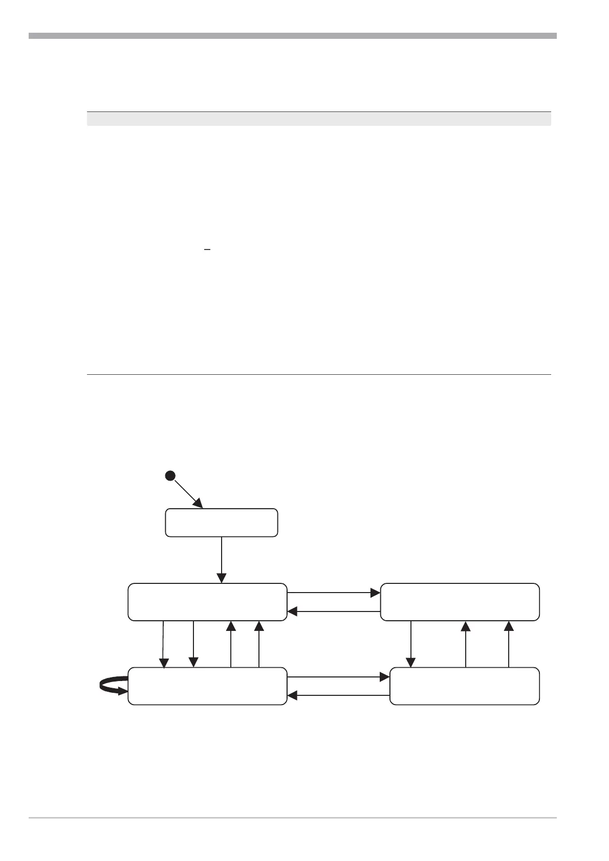
The function flow is described in the following state diagram.
The implemented actions executed at a change-over of states are shown in the
following table.
Operation
Functions for tempering units 8 Operating note KS 50-1 TCont
Power down
Standby /Rem Standby/ Loc
Controlling /
Rem
Loc
T1
T2
T3 T4
T5
T6
T7
T8
T9
T10
T11
T12
T13
T14
Controlling /
 Loading...