1.4 The FM 450-1 hardware
View of module
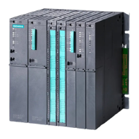
The illustration shows the FM 450-1 module with front connector plugged in.
Labeling strips
Order number
Front connector
Type plate
Diagnostics
and status-LEDs
Version
Figure 1-2 Illustration of the FM 450-1
Order number and version
The full order number of the FM 450-1 is shown on the rating plate.
The abbreviated order number and the version of the FM 450-1 are marked on the top end of the
front of the module.
Diagnostic and status LEDs
The FM 450-1 has 16 LEDs. The LEDs are for diagnostic purposes and indicate the state of the FM
450-1 and its digital inputs and outputs. The following table lists labeling, color and function of
the LED displays.
Table 1-2 Labeling, color and function of the LEDs
Labeling Color Function
INTF Red Internal error
EXTF Red External error
Product Overview
1.4 The FM 450-1 hardware
Counter module FM 450-1
Equipment Manual, 03/2022, A5E03648739-AC 13

 Loading...


