Input lter
For the purpose of suppressing interference, you can assign input lters (RC elements) with a
uniform lter time for the 24 V inputs A*, B*, and N* and for the digital inputs. The following two
input lters are available:
Table 1-1 Input lter
Characteristics Input lter 1
(default)
Input lter 2
Typical input delay 1 μs 15 μs
Maximum count frequency 200 kHz 20 kHz
Minimum pulse width of the count signals 2.5 μs 25 μs
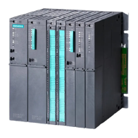
1.3 Fields of applications of the FM 450-1
You can use the FM 450-1 as follows:
The main eld of application of the FM 450-1 is where it is necessary to count signals with high
frequencies and fast reactions must be triggered when a prescribed counter reading is reached.
Examples are:
• Packaging plants,
• sorting plants,
• dosing plants
Example application for an FM450-1
Here a specic number of parts is to be lled into a box. An FM 450-1 counter assumes the job
of counting the parts and controlling the two motors for transporting the parts and the box.
If the box is in the right position, belt A is stopped via the light barrier, the counting process is
started and the motor for belt B switched on. If the programmed number of parts are in the box,
the FM 450-1 stops the motor for belt B and switches on the motor for belt A so that the box can
be transported away. The counting process can start again when the next box reaches the light
barrier
Product Overview
1.3 Fields of applications of the FM 450-1
Counter module FM 450-1
Equipment Manual, 03/2022, A5E03648739-AC 11

 Loading...


